Posted on Leave a comment

مكونات القاطع الكهربائي

مكونات القاطع الكهربائي

مكونات القاطع الكهربائي

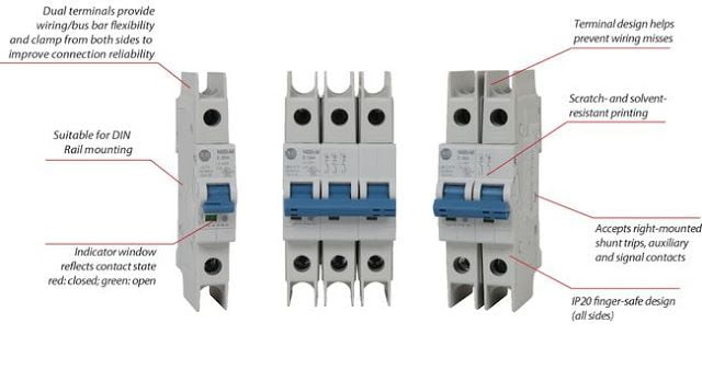
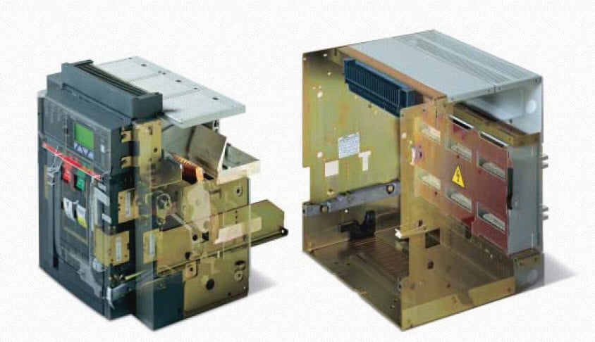
مكونات القاطع الكهربائي، يعد القاطع الكهربائي من أحد أهم الحمايات الذي يستخدم في حماية الأجهزة الكهربائية بكافة أنواعها،

حيث يحتوي القاطع الكهربائي على مكونات داخلية هامة يجب على كل فني ومهندس كهربائي معرفتها، فما هي مكونات القاطع الكهربائي وما دوره في حماية الأجهزة الكهربائية.

دور القاطع الكهربائي في الحماية

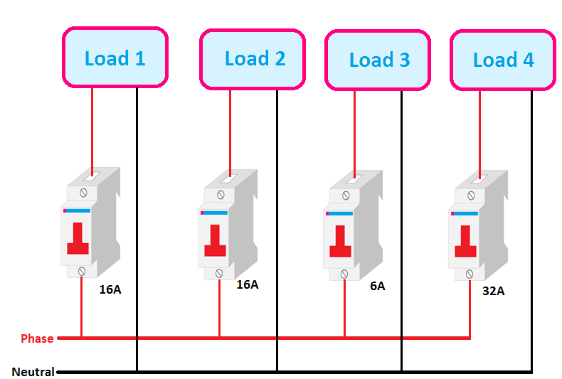
إن القاطع الكهربائي له دور كبير في حماية الأجهزة الكهربائية والأشخاص من خطر التيار الزائد ودارة القصر،

ونظراً لأهميته يستخدم القاطع بكثرة في حماية كافة أحمال الأجهزة الكهربائية، مثل: الفرن الكهربائي والسخانات والمحركات الكهربائية.

مكونات القاطع الكهربائي
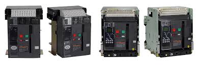
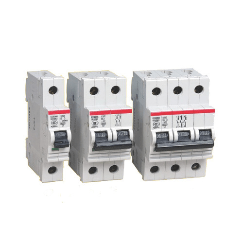
قواطع كهربائية

مكونات القاطع الكهربائي

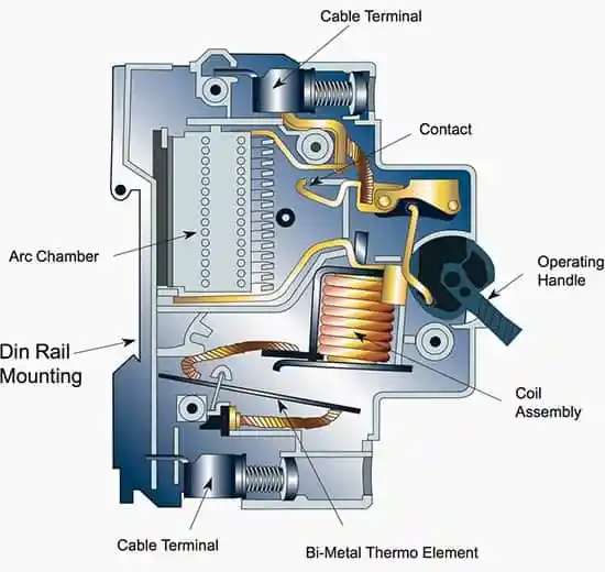
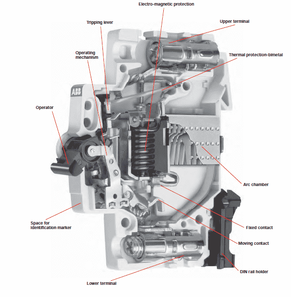
يتكون القاطع الكهربائي ببساطة من عدة مكونات وهي:

نقاط التوصيل:

يوجد للقاطع نقطتين لتوصيل الكابلات أو الأسلاك النحاسية، أحدهما لدخل التيار الكهربائي والآخر يتصل مع الحمل الكهربائي.

نقطة توصيل متحرك داخلي:

هو المسؤول عن وصل وفصل التيار المار إلى داخل القاطع في حالة حدوث دارة قصر في الشبكة الكهربائية أو نتيجة زيادة التيار عن سعة تيار القاطع المقنن بنسبة متفاوتة.

المزدوجة الحرارية المعدنية:

هي المسؤولة عن فصل التيار المار للقاطع عن الحمل نتيجة زيادة التحميل،

حيث أن الزيادة في التيار يتولد عنه حرارة زائدة مسبباً في تقوس الشريط الحراري المكون من معدنيين مختلفين وبالتالي يتسبب ذلك في فتح الدائرة الكهربائية.

الملف المغناطيسي:

وظيفته داخل القاطع هو عدم السماح بمرور تيار لحظة حدوث تماس كهربائي داخل شبكة التمديدات الكهربائية، وهي ميزة في غاية الأهمية وخصوصاً في التمديدات المنزلية.

حيث أنه عند دخول تيار قصر عالي القيمة إلى الملف سوف يتولد مجال مغناطيسي قوي مؤدياً إلى جذب نقطة التوصيل المتحركة إلى الأسفل مسبباً في فصل ذراع القاطع بشكل أوتوماتيكي.

مانع الشرارة:

يتكون من شرائح معدنية متباعدة عن بعضها البعض، ووظيفته داخل القاطع هو التخلص من الشرارة الكبيرة التي تحدث لحظة فصل القاطع نتيجة الحمل الزائد أو التماس الكهربائي.

ذراع القاطع:

يتصل الذراع من الداخل ببعض المكونات الداخلية المتحكمة في الفصل التلقائي نتيجة زيادة التيار أو حدوث تيار قصر، بالإضافة إلى إمكانية رفع ذراع القاطع بشكل يدوي.

مكونات القاطع الكهربائي

استخدامات القاطع الكهربائي

يستخدم القاطع الكهربائي كأداة حماية للكثير من التطبيقات ومنها:

  • حماية الأجهزة الكهربائية المنزلية.
  • حماية كافة التمديدات الكهربائية المتواجدة في المستشفيات والمدارس والمحلات التجارية من أي تماس.
  • حماية المحركات الكهربائية.
  • حماية كافة الأحمال المتواجدة في المصانع الكبيرة والمولات التجارية.

القواطع الكهربائيةشرح القاطع الكهربائي MCCBلمعرفة اخر المنتجات الخاصة بنا وعروضنا المميزة يرجى الاشتراك بصفحاتنا على مواقع التواصل الاجتماعي:

صفحتنا على الفيسبوك=> Gahzlystore

صفحتنا على تويتر=> Gahzlystore

GAHZLY

Posted on Leave a comment

Ex de lighting fixtures and floodlights with LED technology 2022

Ex de lighting fixtures and floodlights with LED technology

1. Introduction It’s appropriate to clarify some beliefs about LED lighting fixtures and,

more specifically, about their use in the…

Ex de lighting fixtures

It’s appropriate to clarify some beliefs about LED lighting fixtures and, more specifically,

about their use in the segment of environments with a risk of explosion and fire:

as men progressed in a continuous research of new technologies through by the technique of breaking stones

for tools and the creation of energy by exploiting the natural flow of the rivers, in the same way Cortem is pursuing

this philosophy approaching new technologies and adapting them to specific projects of research and development

without being fossilized in the past.

First, we analyzed carefully what the LED market was offering us by comparing the production quality of each manufacturer.

The analysis has led to choose products that could give us the appropriate functional guarantees

about the very low “infant mortality” of LED and, therefore, we continued with the

engineering of new lighting fixtures designed depending on application parameters guaranteed by the producers themselves.

These parameters must be appropriate to the right temperature dissipation for an adequate and sustainable use

in terms of the warranty for the customer.In fact, as you can see from the following photos,

the new series of LED lighting fixtures and floodlights designed by Cortem have nothing in common with

lighting fixtures and floodlights for  discharge lamps.

The old “enclosures” are not suitable to be used as a support for LED and do not lend themselves

to dissipate the temperature generated, compromising the proper functioning and durability.

Unfortunately, the “adaptation” and the transformation of old Ex lighting fixtures to new LED lighting fixtures

are very widespread practices in the market. This leads to poor performance and limited benefits in

terms of energy and cost savings for the end user.

The use of appropriate LED lighting fixtures allows to obtain numerous advantages.

Consider that a discharge lamp of 400W can be replaced with LEDs with a power of 160 W,

with an energy saving of about 60%. Furthermore, current Cortem LED lighting fixtures,

in addition to being not much more expensive to lighting fixtures for discharge lamps,

are plenty amortized over time due to the lower costs of maintenance.

The frequency of maintenance, in fact, decreased by 1.7 compared to the activity required for the re-establishment

of a discharge lamps lighting fixtures. It’s well known that a discharge lamp has an average life ranging from 3.000 to 10.000 hours

and then stops working, while LEDs  have an average life of 50.000-70.000 hours and

continues to work, only losing luminous efficiency.

The use of LEDs in the new range of Cortem products allowed us also to get floodlights with T5 class temperature,

much lower than the class temperature of the floodlights with discharge lamps (T2 / T3).

They can therefore be installed in hazardous areas where, until now, it was unthinkable to install a floodlight.

One of the main problems encountered, in order to ensure the safety in the workplace,

is to ensure an adequate level of illumination of the plants. In particular,

the characteristics of electrical equipment installed in areas with danger of explosion are designed with even

greater attention to get good illumination and reduction of risk conditions.

About 80% of all our sensory impressions are of optical nature and they need of light as a vehicle of information.

Good lighting, therefore, not only facilitates the vision and the recognition, but it greatly reduces the danger of accidents.

The devices that are installed in hazardous areas must therefore ensure, in addition to explosion protection,

the proper lighting required for the execution of all work operations in conditions of maximum security and must

have other characteristics, such as the reduced need for maintenance in order to minimize

risks associated with the equipment operation.

The LED is a light-emitting diode, otherwise, an optoelectronic device that uses the optical properties of

some semiconductor materials to produce photons through the phenomenon of spontaneous emission.

The first LED was developed in 1962 and, from that moment on, the technology has made great strides.

Today we have components that can be effectively used for industrial lighting.The main advantages of using

LEDs in lighting fixtures can be summarized as follows:

  • Reduced dimensions and lightweight than conventional lighting fixtures of equal power
  • High efficiency and energy savings
  • Long life (approximately 100,000 hours) with consequent reduction of maintenance costs
  • Resistance to vibration
  • No UV emission
  • Instant restrike
  • Excellent performance in harsh application
  • Anti-light pollution

In the specific case of the use of such components in the construction of lighting equipment used in classified areas,

the main advantage lies surely in the long duration that, in addition to being convenient in economic terms,

means a smaller number of maintenance interventions (lamping) on lighting equipment.

This is very positive in terms of safety, because, as you know, every intervention on equipment installed

in areas with risk of explosion increases the risk level of the system.

Another advantage of LED is that, unlike other sources of artificial lighting, once reached its limit of life,

not shut down abruptly, but continues to operate with a luminous flux reduction. This is synonymous of safety,

especially in those places of the plant where the lighting is fundamental to prevent accidents or injuries.

2.1 The light spectrum

The light spectrum of white LEDs of the latest generation, such as those used for the realization of our LED range,

is about as close to sun light spectrum. In the diagrams below, you can appreciate the differences between

the spectrum of sunlight and of other light sources, such as fluorescent lamps, discharge lamps and white LEDs.

For our LED products, we use only Cree LEDs with maximum efficiency,

in order to obtain the best light quality and the maximum lumen output.

All lighting fixtures have a CRI (Color rendering index) > 70 and a standard light color cool white 5700° K.

For special needs, can be requested a different color temperature.

After analyzing the characteristics associated with the use of LED technology,

let’s see the features of LED lighting fixtures that allow their use in classified areas for the presence of an explosive atmosphere.

For use in areas with danger of explosion is obviously necessary that the lighting equipment are designed,

built and certified according to technical regulations implemented by the ATEX Directive 94/9/ EC

and by the new ATEX Directive 2014/34/EU entered in force on March, 30th 2014. It will repeal,

with effect from April 20th 2016, the ATEX Directive 94/9/EC. The protection methods that can be used are the following:

  • Ex “d” explosion-proof: the philosophy of this method is based on the consideration that it’s not possible to prevent a gas to spread everywhere. The main advantage of this method of protection is that the electrical elements installed inside the lighting fixture, constructed to contain any explosion, are common components easy to find.
  • Ex “e” increased safety: the purpose of this method is to ensure security measures to prevent the formation of arcs or sparks. The main advantage of this method of protection is its simplicity of construction and, above all, applications. One of the disadvantages is the fact that the components, besides not being easy to find on the market, must be individually protected.
  • Ex “m” encapsulated: the purpose of this method is to prevent an explosive atmosphere may come in contact with ignition sources by encapsulating the equipment.

Cortem has designed and manufactured a full range of lighting equipment and floodlights that use the latest LED technology generation.

The LED technology in the coming years, will certainly replace other sources of

artificial lighting designed to obsolescence because of operating costs, environmental problems and ease of use.

4.1 EWL series lighting fixtures and floodlights – High Bay

EWL series consists of three models of High-bay lighting fixtures, EWL 70, EWL-80, EWL-100,

and three models of floodlights, EWL-70/ .., EWL-80/…, EWL-100/… with different optics:

Narrow (10°), Medium (20°) and Wide (40°).

Through the use of optics with different angles, you can get the optimal light beam in well-defined areas.

This allows maximum versatility of use, ensuring the proper illumination of the workplace.

A new feature for these lighting fixtures is the possibility to be powered at 24 VDC.

For the first time in the lighting history of areas with danger of explosion,

it’s available a lighting system with a lighting efficiency comparable to that obtainable with discharge lamps,

powered directly with alternative systems such as wind turbines, solar panels, battery systems.

As we said in the introduction, the LED lighting fixtures must be designed and constructed specifically.

The construction of bodies in aluminum alloy, designed with elements of heat dissipation,

is the key to obtain an efficient and long lasting system.

The housing of the feeder must be correctly calculated in terms of volume to allow easier heat dissipation.

In the picture below you can appreciate the thermo-graphic survey.

The finned body, made of aluminum alloy, acts as a heat sink for the LED plate mounted directly inside,

on the body of the lighting fixture allowing it to dissipate more quickly and effectively

the heating generated by the operation of the LEDs themselves.The design of the lamp body,

in addition to being functional to the duration of the system,

has allowed obtaining equipment with high luminous efficiency in relation to the maximum surface temperature.

This is a very important factor for the installation of lighting fixtures in places of danger,

containing gas or powders at low ignition temperature.

A further saving is obtained thanks to the fact that, while discharge lamps requires a preheating time for their complete ignition and,

for this reason, the lights of a plant are lighted up 24 hours, LEDs have an Instant Restrike.

A LED system can be effectively connected to automatic ignition system in case of low light,

allowing the use only for periods actually needed and, consequently, with a further saving of energy costs.

LED technology allows also adjusting the light output according to the real needs of the room to be lighted (dimming).

EWL series features with ‘Ex de’ method of protection for Gas and ‘Ex t’ for Dusts.

This choice allows powering the equipment through a ‘Ex e’ cable gland and without the need to perform sealings on field.

A tapped hole opposite to the entrance of the cable, allows the connection through wiring.

It’s now available a new version of the EWL-80 series, the EWL-801, both in lighting fixture and floodlight version.

The EWL-801 makes it possible to obtain, with the same size but with a power consumption of 110W,

a lumen output almost twice respect to EWL-80, 10100 lm compared to 6050 lm,

and a maximum light intensity much higher: 4330 cd for the lighting fixture version and 118670 cd (EWL-801/10),

51680 (EWL-801/20) and 20900 (EWL-801/40) for the version with optical concentrating of the light beam.

The series EWL has been certified and complies with the requirements of the following standards:

• EN/IEC 60079-0 Electrical apparatus for explosive atmospheres due to the presence of gas – Part 0:

General requirements;

• EN/IEC 60079-1 Explosive atmospheres – Part 1: Equipment protected by flameproof enclosures “d”;

• EN/IEC 60079-7 Explosive atmospheres – Part 7: Equipment protection by increased safety “e”;

• EN/IEC 60079-31 Explosive atmospheres – Part 31: Equipment with protection by enclosure “t” for use in presence of combustible dust.

It was also subjected to the tests required for the photo-biological risk assessment regulated by IEC/EN 62471 standards.

These tests measure the amount of emissions of UV, blue light and infrared radiation (IR),

which may cause damage to the skin and eyes (retina and cornea) operators.

The lighting fixtures and floodlights EWL series are EXEMPT from the photo-biological risk.4.2 EVL series lighting fixtures

The new LED compact lighting fixtures EVL series features Multichip LED formed from a matrix of LEDs

connected together and covered with a layer of diffused phosphorus. This technology allows obtaining high

values of lumen output and the installation at low heights, without the risk of disturbing the operator.

The EVL series consists of three lighting fixtures sizes: EVL-60, EVL-70 and EVL-80.

It represents the LED alternative for all those areas in which it was usual to use lighting fixtures with discharge

lamps of low and medium power up to 400W.

It’s equipped with fins that act as a heat sink and the electrical connection is easier thanks to a ‘Ex e’ terminal box,

which allows the entry with a ‘Ex e’ cable gland (no barrier). In addition, a tapped opposed hole allows the loop in/loop out facility.

In the following table, we can compare the power of EVL series lighting fixtures and of traditional lamps.

You will immediately appreciate the savings you can get.

4.3 EVE-L series lighting fixtures with LED remote phosphor technology – Low Bay

EVE-L series Cortem lighting fixtures are designed to provide an optimal replacement to the conventional incandescent lamps from

50W up to 200W. It’s available in two sizes: EVE-5050 end EVE-5060.

The peculiarity of these new lighting fixtures consists in the use of the LED Remote Phosphor Technology

on explosion-proof lighting fixtures.

This represent an absolute evolution in the world of LEDs and an important step forward in terms of energy efficiency,

lighting efficiency and chromatic yield quality.

The LED Remote Phosphor Technology is based on a yellow semi-spherical light diffuser that, when the lighting fixture is on,

absorbs the light produced by the internal LEDs and releases white light.

The EVE series allows to replace the lighting fixtures which use incandescent and energy-saving lamps with a

long lasting light source that ensures a better efficiency and an equal brightness comfort.

4.4 FLF-…L and FLFE-…L series lighting fixtures

Lighting fixtures for LED tubes FLF-…L (Ex d) and FLFE-…L (Ex de) series have two low copper content aluminium

heads with G13 lamp holder, a tempered borosilicate glass tube, that is resistant to changes in heat,

and a white painted aluminium reflector.

Both the series are available with one tube or with two tubes.

FLFE-…L series, in ‘Ex de’ way of protection, features an

“Ex e” terminal board housing that allows entry to the fixtures with a cable gland with an

“Ex” seal (normal), while FLF-…L series, in ‘Ex d’ way of protection, as specified in the appropriate installation standard

(EN/IEC 60079-14), the entry to the fixture must be through an Ex “barrier” cable gland (sealed)

or, in the case of a conduit system, with an EYS, EZS series sealing fittings.

The use of LED tubes, which have the same dimensions of fluorescent ones, allows to obtain economy in operating costs,

due to their long life, high-efficiency lighting, thanks to directional light,

and LED light quality with a color rendering index of 85 (CRI).Furthermore,

LEDs do not ionize the particles of air around the lamp and do not attract, then, the dust particles suspended in the air.

The round cross section of the lighting fixtures provides a better “Cx” coefficient with less resistance

to the wind and less accumulation of dust. FLFE series has been designed to facilitate and speed up maintenance operations.

As the electrical components are housed on a frame with guides,

re-lamping is quick and efficient. Furthermore,

the different types of mounting attacks and the absence of sealing fittings make the lighting fixtures particularly well performing.

4.5 EXEL-L series lighting fixtures (Work in progress)

EXEL-L series increased safety lighting fixtures for LEDs tubes are suitable to be installed in hazardous areas

1, 2, 21 and 22 where a high degree of protection and resistance against corrosion is required such as

in chemical and petrochemical plants, off-shore and on-shore plants, processing areas in food industries

etc… EXEL-L series is polyester made, with ‘Ex e-mb’ method of protection for LED tubes with remote

phosphor diffusers to reduce glare.

The through wiring double ended makes installation on field easier and

faster than normal lighting fixtures.

The transparent cover is clipped into place on both sides of the fixture body with 8

clips on the 785 mm model and 14 clips on the 1370 mm unit.

This ensures excellent protection against dust and water over time despite of degradation caused by ageing.

4.6 EVML-50 series lighting fixtures – Low Bay (Work in progress, end 2014)EVML-50 lighting fixtures,

in the design development phase,

have been conceived to offer a Low Bay lighting fixture that could replace incandescent equivalents at lower costs.

They are suitable for the illumination of small areas in which it’s necessary to limit the obstruction such as tunnels,

passages, corridors, stairways, perimeter walls and command and control cabins.

The EVML-50 series features the ‘Ex e mb’ method of protection:

the electronic board and the LEDs are protected with silicone of high transparency.

4.7 EVOLED series lighting fixtures (Work in progress)

The new EVOLED series lighting fixtures are designed for the internal lighting of boilers,

tanks, evaporators, silos, storage tanks, pipelines or other containers present in all those areas where hazardous vapors

, gases, dust or other fuels are present during the normal operation of a plant.

In addition to ensuring low power consumption and light efficiency,

the lighting fixture is provided with an external switch for an easy switching on and off after installation.

4.8 SLED series floodlights (Work in progress)SLED series rectangular floodlights, in the design development phase,

are equipped with “Wide area” optics for the symmetric and asymmetric illumination of industrial areas,

in general, and of hazardous areas.

Designed with ‘Ex m’ method of protection (encapsulation), SLED series floodlights are characterized by size,

weight and power consumption much lower than the floodlights fitted with conventional discharge lamps.

Safety is essential for workplaces and, especially in areas with potentially explosive atmospheres, the risks are very high.

Any system, therefore, that allows to reduce the level of risk is always well accepted.

Furthermore, if there are savings in money and energy, then the advantage is total.

The LED lighting in industrial sector is a path just started, but it’s definitely the

way to be followed to ensure a future of light and safety.

We summarize here, in conclusion, the main advantages that presents the range of Cortem’s

LED products with which we set ourselves several steps ahead in terms of technology against competitors:

  1. Energy saving with maximum efficiency, more light and less consumption.
  2. Longer life than conventional bulbs and, thus, reducing of maintenance costs.
  3. Savings of plant costs, lower costs to bring energy to the lamp.
  4. Directional light and superior quality allow a better identification of the colors of illuminated objects. Safety in the workplace.
  5. Use in lighting systems at low voltage (24Vdc).
  6. Resistance in the ON / OFF cycles.
  7. No Light Out for the security in the workplace.
  8. Resistance of the components to the electrical and mechanical stresses.
  9. Less weight, less volume, easier handling.
  10. Excellent heat dissipation for longer life of the LED.
  11. Possible electronic control of the light output (dimming).
  12. Respect for the environment, compliance with the standard anti-light pollution.
  13. Excellent performance in extreme climates.
  14. Immediate availability of the maximum light output power.
  15. Very low mortality of LEDs.
  16. Lower temperature classes.
  17. ‘Ex de’ method of protection allows the entry of the cable without realizing any conduit system with sealing.
  18. Possibility of replacing the LED plate with a more advanced technology (Future Proof).
  19. In the remote case of failure of one of the LEDs, the Ex safety remains unchanged.
  20. Multifunctional. From lighting fixtures to floodlight with the sole plate replacement.
  21. Guaranteed 50,000 hours (25° C ambient temperature).
  22. Suitable for classified areas as IIB and IIC.
  23. 100% recyclable.
  24. No flickering.
  25. Absence of hazardous substances such as the mercury for fluorescent lamps.

Electrical transformers

We are pleased to have you visit our pages on social networking sites,

where we publish exclusive offers on our website.

Our Facebook page here .

Our Twitter account is here .
Posted on Leave a comment

What are the differences between LED chips ? 2

q

What are the differences between LED chips ?

Which type should I choose?

LED strip lighting can be manufactured using a variety of different LED chip types.

Below, we’re going to explain the main differences between them –

by comparing the most commonly used chip types on the LED tape


LED chip


What does the number of an LED chip mean?

LED chips (also known as surface mounted diodes or SMDs) are all identified by a four-digit number.

This code is less complicated than it looks – it simply indicates the size of the LED chip.

For example,

the dimensions of SMDs on LED strip lights are 5.0mm x 5.0mm.


Which is the best LED chip?

LEDs like s, s, s and s aren’t really different types of chip at all – they’re simply different sizes.

Each has its own spec: different power requirements and output brightness.

The best choice depends on what’s right for your project.

You can find out more about each LED chip below.


The LED chip explained

Measuring 3.5mm x 2.8mm, the SMD is a smaller chip than the LED strip SMD.

You will most often find chips on 12-volt LED strips, drawing 4.8 watts

(also known as 4.8w p/m or 5w p/m LED tape) with 60 SMDs per metre.

These strip lights output around 330-360 lumens per metre,

depending on colour (equivalent to a 40w halogen) – enough to produce a smooth,

bright effect when shining onto any surface.

InStyle offer red, green, blue, amber, and both warm and cool white SMDs as standard colours.

(We can also supply other white colour temperatures, made to order.)

60 SMD p/m LED strip lights are typically used for feature lighting –

such as plinth or coving lights, in homes, bars, restaurants, hotels and other locations.

Though less common than standard 60 SMDs p/m LED tape, SMDs are also used on LED strip lights with 120 chips per metre.

Pulling 9.6 watts (known as 9.6w p/m or 10w p/m LED tape),

these tapes are available in the same range of colours. Light output is exactly double that of 60 SMDs p/m tape

– they have twice as many LEDs – so that’s around 660-720 lumens per metre, depending on colour.

120 SMD p/m LED strips are used for the same kind of feature-

lighting applications as its standard alternative. We recommend them for locations with strong ambient light,

where more brightness is needed than the 4.8w p/m can produce.

The cut points for our 60 SMD-per-metre LED strips are 50mm apart.

The 120 SMD p/m strips have cut points at 25mm intervals.

Both types are also available in waterproofed versions (IP67-rated).

Safe to touch

SMDs do not give off a lot of heat – you can safely touch them.

Even so, the 60 LED p/m tape requires PCBs (printed circuit boards) at least 8mm wide, and the 120 LED p/m tape

should use 2-ounce thickness PCBs.

As long as your LED strips meet these minimum specifications,

they can be simply installed anywhere because they have a sufficient heat sink not to require an additional aluminium extrusion.

There are many manufacturers of SMDs.

Epistar-branded SMDs are extremely high quality and give you the brightest SMDs on the market.

They offer excellent colour consistency and reliability, with a life of 50,000 hours at 70% output.

Cheaper alternatives are less bright and less reliable, and are prone to colour inconsistencies within the reel and between reels.


Double-power SMD explained

Double-power SMDs are the same size as standard-power LEDs.

They are available in the same colours, drawing twice the power to give twice the output.

LED strip lights manufactured using double-power SMDs have 120 LEDs per metre and pull 19.2 watts per metre

.(also known as 19.2w p/m, or 20w p/m).

Double-power LED strips use a 2-ounce 10mm wide PCB to disperse heat effectively,

in order not to require an extra heat sink when installed.

These LED strips are only available for 24-volt systems, as this carries current better.

Lumen output is around 1320-1440 lumens per metre (depending on the colour).

Because of its high brightness, we recommend this LED tape as general lighting, or to replace fluorescent tubes and halogens.


The LED chip explained

Measuring 50mm x 50mm, the SMD is larger than the SMD.

These dimensions mean that each SMD is big enough to house four separate LED chips (sometimes called ‘quad LEDs’).

LED chips are often used on 60 LED-per-metre strip lights,

pulling 14.4 watts at 24 volts (commonly called 14.4w p/m or 15w p/m LED tape).

With an output of around 990-1080 lumens per metre, depending on colour,

this tape gives you a smooth, bright effect when shining onto a surface.

Available colours are:

  • warm and cool whites (other Kelvins requirements can be manufactured on request)
  • red, green, blue, and amber single-colour
  • and also colour-changing – either RGB or RGBW (red, green, blue, white), using ‘tri’ / ‘quad’ chips (three or four LED chips in one).

These 60 SMD p/m LED strip lights are typically used for general lighting applications, such as corridor lighting,

replacing fluorescent tube lighting, in homes, bars, restaurants, hotels and other locations.


What are the differences between LED chips ?SMDs used in RGB LED strip lighting

The SMD is actually a ‘tri’ chip, meaning it has three smaller chips in every SMD.

So each white LED actually has three white chips inside.

s can also be used for colour-changing LED tape, with red, green and blue chips inside each LED.

By linking this type of RGB LED strip light to a controller, you can mix any shade of any colour you choose.

(RGBW tape is similar, but uses ‘quad’ LEDs, with an additional white chip.)

RGB LED strip lights are available in two types:

  • 30 LEDs per metre (known as 7.2w p/m or 7.5w p/m LED tape) outputs up to 500 lumens per metre and is ideal for feature lighting such as covings, plinths in homes, hotels, restaurants and bars.
  • 60 LEDs per metre (aka 14.4w p/m or 15w p/m LED tape) produces up to 1000 lumens per metre, perfect for full wall-washes such as bar frontage, back bars in restaurants, clubs, or the home.

We can supply both types of LED tape (30 and 60 LED p/m options) in waterproofed versions (IP67-rated).

The cut-points on both are spaced at 100mm intervals.

Branded Epistar SMDs are the highest quality LEDs on the market. They provide the best brightness, colour consistency and reliability with 70% output at 50,000 hours.

Using cheaper alternatives instead, you’ll get dimmer and more unreliable LEDs that output inconsistent colours within each reel and also from reel to reel.


The LED chip explained

A recent development, SMD LED chips are much smaller and much more efficient than many earlier SMD models.

The smaller size of the diodes (just 3.0mm x 1.4mm) means it’s possible to fit more of them on a length of PCB strip

– offering more brightness, without the need for more power.

At InStyle, we use SMDs in the manufacture of our specialized dual-white colour-temp changing (CCT) LED tapes.

Their compact size allows two LEDs producing different white shades to be positioned very close beside each other,

making it possible to mix a varied palette of different white-light tones from a single LED tape.

(A similar set-up to RGB/RGBW colour LEDs.)


The LED chip explained

The SMD is a new choice on the LED market. Instyle LED have now tested  chips fully, to confirm their reliability and efficiency.

2.8mm x 3.5mm in size, the chip is so far only available for white LEDs.

In practice, you can view  SMDs as a more efficient replacement for the –

producing 20% more light but drawing less wattage. Each  SMD pulls 0.2w

(a SMD pulls 0.24w), so that’s around 12 watts per metre compared to 14.4w for the SMD,

based on 60 LEDS p/m. Because the SMD is smaller and doesn’t get as hot,

it’s possible to mount up to 120 LEDS p/m – that’s 24w p/m – giving up to 2600 lumens per metre!

  • Cool white SMD 60 LEDS (14.4w p/m) = 1080 lumens per metre
  • Cool white SMD 60 LEDS (12w p/m) = 1300 lumens per metre
  • Cool white SMD 120 LEDS (24w p/m) = 2600 lumens per metre

InStyle’s LED strip lights are mounted on 2-ounce PCBs (10mm width) for better heat dispersion, superior reliability and longer life.

So this really is a product for the future.

We supply both 12w and 24w p/m LED tapes, in warm white, cool white or any custom white shades.

We also offer splashproof IP65 and waterproof IP67 heatshrink-coated options.

Now that chips have been available long enough to prove themselves,

we confidently predict that more people will switch to them from SMDs, as they realise the advantages.


The LED chip explained

The SMD has been around for several years, but has only recently become an option in the LED tape market.

(Before that, most LED suppliers used these chips on thick PCB rigid strips rather than LED tape, as they require a very good heat-sink.) SMDs have dimensions of 5.6mm x 3.0mm.

A larger LED doesn’t always mean brighter – but in this case, the chip outputs far more light than the more common SMD.

High-quality chips on 60 LED p/m tape can produce up to around 2700 lumens.

(To give an idea of the importance of component quality, lower grade SMDs output less the 2000 lumens per metre.)

LED tapes mounted with SMDs generate more heat than some other LED chips.

Because of this, we recommend installing SMDs with either an aluminium extrusion,

additional heat-sink backing or a thicker and wider PCB. Without these, your LED strip lights may work initially

– but brightness will likely reduce quickly, because overheating is the biggest adverse contributor to the brightness and lifespan

of LEDs. Used 8 hours per day, overheating could see you lose up to 20% in brightness per year!

Instyle LED always uses thicker, wider PC boards and A-grade Epistar-branded SMDs,

so you can always rely on the quality of our LED tape components. We offer this product in all shades of white.

We don’t advise the use of heatshrink to waterproof SMDs, as it can lead to overheating issues.


Summary of LED chip types

In the end, the type of SMD chip doesn’t matter – as long as it can meet your requirements.

InStyle recommend branded Epistar LEDs for the reasons we discussed above (brightness, reliability and colour batching).

When purchasing LED strip lights, you should ask yourselves these questions:

  • Do you want feature lighting, task lighting, colour changing, waterproof, etc?
  • Dimmable or non-dimmable?
  • What colour do you want?
  • How bright do you need the LED strips?

كيفية توصيل القواطع الكهربائية المنزلية

lightning
We are pleased to have you visit our pages on social networking sites, where we publish exclusive offers on our website.

 Facebook page here.

Twitter account is here.


Posted on Leave a comment

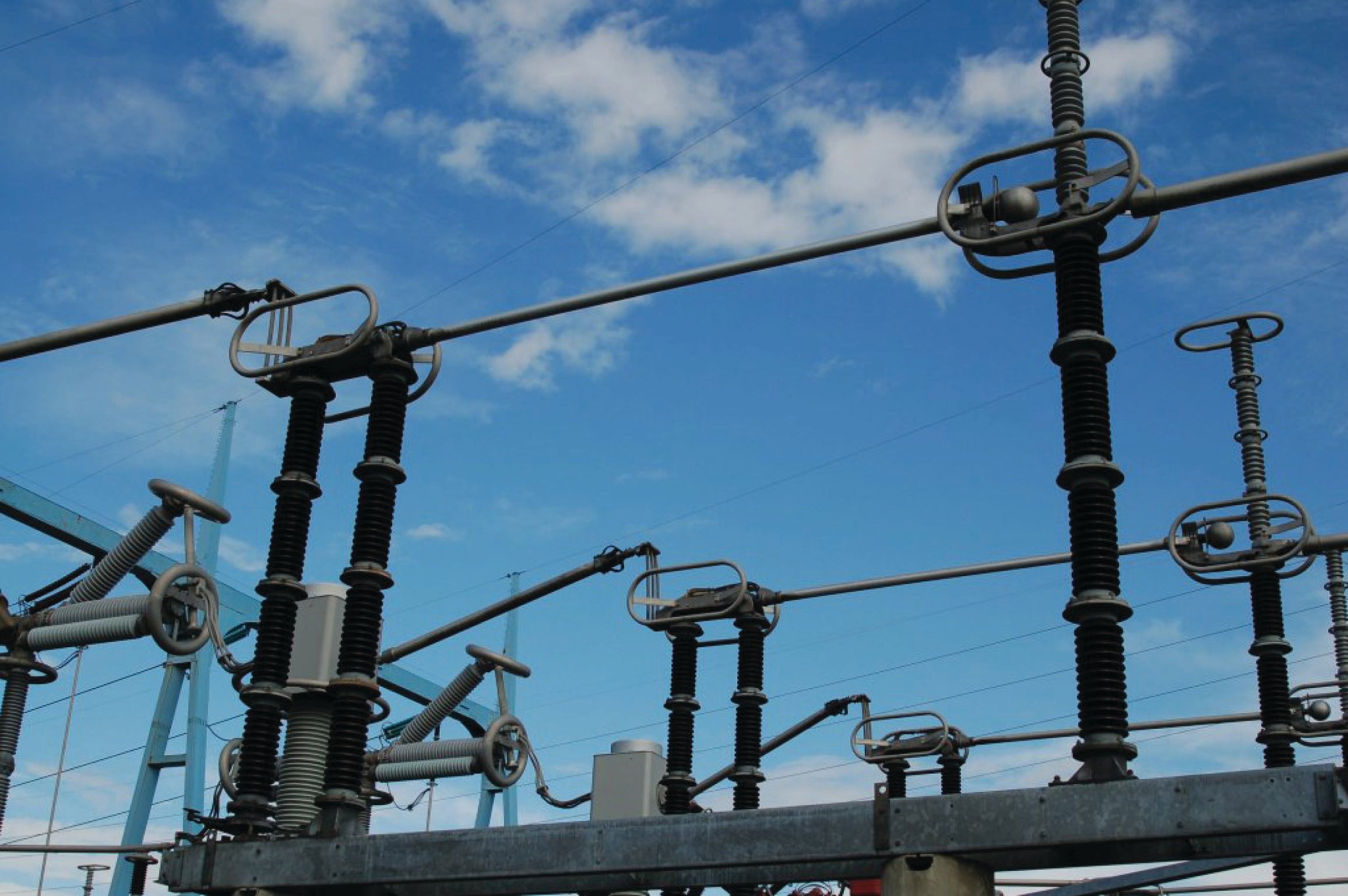
difference between air switch and knife switch 1

difference between air switch and knife switch

We often see electric bus switches for rural households including air switches and knife switches.

Knife switches are not common in urban households, but they are still very common in rural households.

However, in recent years, knife switches have gradually decreased and gradually replaced by air switches.

Two kinds of switches have their own advantages, so should you choose one when choosing a switch?

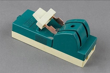
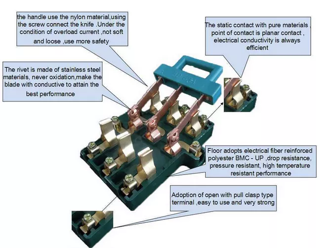
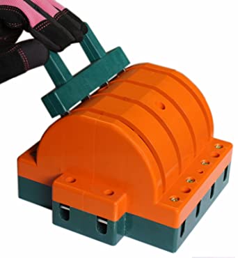
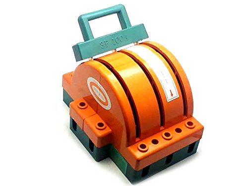
Knife switch internal structure

The above kind of switch is a knife switch often used in the family.

In addition to the separation function, it also has an overcurrent blown fuse (sheet).

This kind of switch has been used by most families because of its simplicity and low price. .


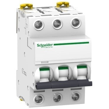
air switch

Air switch is also called air circuit breaker, and it is also a kind of switch, but this kind of switch has the function of extinguishing arc in addition to the function of separating circuit and overcurrent fuse of knife switch.

What is arc extinguishing? Extinguishing an arc means extinguishing an arc.

Arc is the electric spark we see when we close or open the switch.

Electric spark is a relatively slight discharge phenomenon in electric arc.

Because this air switch has an arc extinguishing function

, no electric spark can be seen when the switch is closed or opened, so its safety is better than that of a knife switch.

So should I choose a knife switch or an air switch?

It depends on the situation

First of all, knife switch and air switch have their own advantages and disadvantages:

Comparison of advantages and disadvantages of knife switch and air switch

Switch knife Air switch
Advantage
a. Low price
b. Can clearly see the breakpoint of the circuit
a. With arc extinguishing capability, high safety
b. After the circuit is disconnected, it is not necessary to replace the originals when closing, and the reuse rate is high
Disadvantage No arc extinguishing function, easy to see electric sparks, and the fuse needs to be replaced The price is more expensive, the service life is shorter than the knife switch

So, which switch you use depends on which effect you want.

If you want to be able to see the obvious disconnection point of the circuit

(can clearly see the disconnection point, people are more relieved) choose the knife switch.

After all, the disconnection point cannot be seen after the air switch is disconnected.

As for the disconnection, it depends on Whether the air switch is in the normal state;

if you want a higher safety and can extinguish the arc, then choose the air switch

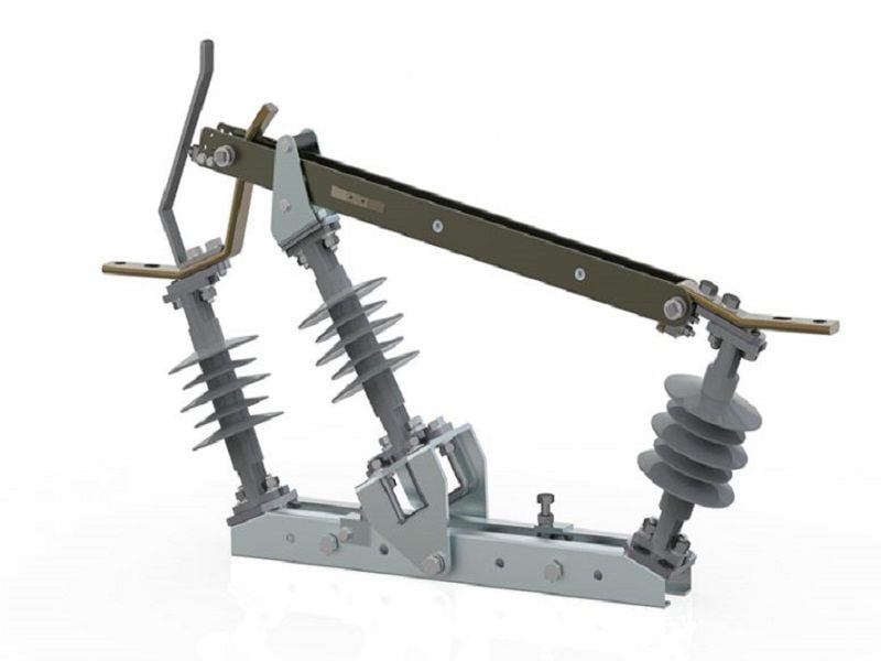
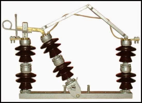
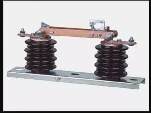
Air Break Switch: Types and Uses


An air break switch is a type of switch that makes use of air as a dielectric and arc quenching medium.

The contacts of an air break switch open in the air.

Here, the arcing problem produced while opening the switch is resolved with the help of compressed air.

These types of switches are generally operated at low voltage levels,

i.e., voltage ranging from 450V up to 35kV.

The current range of air break switches lies between 800 A and 10KA.

The air pressure used by the air break switches ranges from 4 to 60 atmospheres.

It can also be said that an air break switch is a switchgear device that makes use of air as an interruption medium.

Working of an Air Break Switch

An air break switch is typically used to open the circuit under the load.

The arc that gets produced during the process of opening the switch is quenched in many ways.

It can be extinguished by moving the contacts away from each other or by supply interruption.

Usually, the arc is put out with the help of lengthening of the arcing horns present in the structure of the switch.

These arcing horns are nothing but the pieces of metals between which the arc is formed.

As the switch gets opened, the arcs tend to move far from each other, eventually breaking out.

The main components of an air break switch include an arc extinguisher

, a reservoir provided with a supply of compressed air, and an electro-pneumatic actuator.

The arc extinguisher is connected to the compressed air reservoir with the help of an insulated line.

It is used to quench the arc produced between the movable and the fixed contacts.

The de-energized electromagnet tends to open the air blast valve through a system of various pneumatic devices.

This helps supply the compressed air from the reservoir to the arc blowout chamber through the airline.

This compressed air tends to act on the piston of the movable contact and separates the movable contact from the fixed contact.

The arc that gets formed due to the opening of the contacts of the switch is required to be extinguished.

The compressed air from the chamber is used for the purpose of arc quenching.

The compressed air is directed through the outlets of the contacts to the gas escape channels.

After some time, the air enters the cylinder of a pneumatic actuator and quenches the arc.

After the arc extinguishes, the compressed air actuates the piston and breaks the isolating switch contacts.

The contacts are closed and the incoming of the compressed air is then cut off.

When the electromagnet gets energized, the valve opens and the compressed air is allowed to pass through the insulated airline.

The air enters the cylinder, acts on the piston, and closes isolating switch contacts.

Some of the air break switches are manufactured with air-filled isolating switches.

Such switches consist of contacts that are packed in an insulated casing.

The switch gets filled up with compressed air after being disconnected.


Types of an Air Break Switch

The air break switches can be broadly classified into two categories,

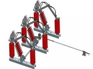
namely single-pole air-break switch and the gang operated air-break switch.

Single-Pole Air Break Switch

A single-pole air break switch provides an opening for only one conductor.

The working of a single-pole air break switch is similar to that of a normal air break switch.


Gang Operated Air Break Switch

A gang operated air break switch is used when the opening of more than one conductor at a time is required.

Here, all the switches tend to open and close together.


Uses of an Air Break Switch

An air break switch is used in a number of commercial and industrial applications as given below:

1. Air break switches are typically used for switching and isolation purposes.

2. Air break switches are generally installed in the distribution networks as

a switching point to make or break connections between cables, transformers, and other high voltage electrical devices.

3. Air break switches are used in overhead power transmission lines.

Here, these switches are mainly used to perform on/off switching

by connecting the power system of a part of the overhead line to the main distribution line or

by disconnecting it from the main distribution line.

This allows the user to simply isolate a part of the overhead line without affecting the rest of the power transmission system.

4. These types of switches can also be used in power generation lines.

5. In certain power distribution systems, air break switches tend to provide crucial point isolation.

6. It is typically used to provide overcurrent and short circuit protection.

7. They are used in industrial plants for various control and safety operations.

Advantages of an Air Break Switch

An air break switch is advantageous in the following ways:

1. An air break switch is more effective than ordinary switches.

2. The reliability of air break switches is significantly high.

3. Air break switches can be operated manually as well as automatically depending on the requirement.

4. The maintenance of air break switches is relatively easy and cheap.

5. The air break switches are capable of fast breaker and switching operations.

6. These switches do not cause fire and explosion hazards.

7. An air break switch does not require a compressor.

8. These switches allow the user to maintain the stability of the operation.

Disadvantages of an Air Break Switch

Certain limitations or disadvantages of an air break switch are listed below:

1. They are quite heavy and bulky in nature.

2. The air break switches are less efficient for deionizing and lengthening action at high currents.

3. These types of switches are not suitable for modern power systems.

4. Air break switches require high capacity equipment for the storage and production of compressed air.

5. There exist chances of air leakage resulting in reduced pressure.

6. Air has comparatively lower arc extinguishing properties.

7. There are chances of a high rate rise of re-striking voltage and current chopping.

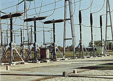
Air Break Switch – Types and Uses

An “air break switch’ is a switchgear device that uses air as the dielectric.

Air Break Switches (ABS) are widely installed throughout distribution networks for use as both isolation or switching points.

They are usually employed in outdoor installations.

Special Arcing Horns are provided to quench the arc which occurs when the current is interrupted.

These switches are usually operated by a handle which is located at the ground level.

Their operation can also be mechanized.

Use of Air Break Switch

Air Break Switch Disconnectors are a vital part of any overhead line network,

providing crucial points of isolation.

Most overhead line networks are designed so that when a fault occurs or maintenance work needs

to be carried out it is relatively simple, by means of a systematic series of switching operations,

to isolate a certain section of the overhead line.

When this switching process is carried out it is absolutely imperative

that the Air Break Switch Disconnector is reliable and effective.

The triple pole air break switch is gang operated and designed for outdoor application.

The switch is intended for switching of the Transformer, Overhead lines, and Cables from the distribution system.

Types of AB Switch

Air break switches can be of two types
  1. Single Pole Air Break Switch
  2. The Gang Operated Air Break Switch

It can be operated manually using either a handle/ratchet mechanism or an insulated

‘hook stick’ made either of wood or fiberglass.

Air break switches are designed for switching under load,
but there is often a noticeable arc associated with switching.

Air Break Switches are installed in either horizontal or vertical (Pole Top or Mid Pole) configurations.

Air break switches can be found either in substations or out on the distribution system

– either pole top or in pad-mounted metal enclosures.

Breakers, Reclosers, and Disconnectors

A Circuit breaker is a switchgear device that operates automatically and is specifically
intended to interrupt short circuit currents (in addition to ordinary load currents).

Circuit breakers can be designed using air, oil, vacuum, or SF6 gas as the dielectric.

Circuit breakers are only found in substations.

1. Recloser

A recloser is a lot like a circuit breaker both in function and also the choice of the dielectric.

Reclosers typically have less short circuit interrupting capacity than breakers,

but they are designed to automatically reclose to restore the interrupted circuit.

The reason for that is that most

(typically, more than 80% of the faults on overhead distribution circuits are self-clearing

(tree branches, small animals, etc) and can be restored if the circuit is allowed to remain de-energized for 10-15 seconds

so that the ionized air in the vicinity of the fault can dissipate. Reclosers are much less expensive than breakers.

2. Sectionalizer / Isolator

A sectionalizer/isolator is a device that is applied out on a distribution circuit that

is intended to determine that a fault is located downstream of the recloser.

The principle of operation is that once the sectionalizer/isolator makes the determination that the problem is downstream,

it can open, and then an upstream reclosing device (either a recloser or a circuit breaker)

can automatically reclose to restore service to those loads that are upstream of the sectionalizer.

A sectionalizer/isolator doesn’t have any current interrupting capability but instead

relies on the upstream device to interrupt fault current.

3. Disconnector

A disconnector is simply a device that is used to disconnect a load.

It can be an air break switch, or it could be a circuit breaker.

The name implies the function and is not necessarily descriptive of the device itself.

The term ‘isolator’ is a synonym for disconnector.


Knife Switch

manually operated electric switching device that makes, breaks, or changes the course of electric circuits.

The switch can operate either under load

, at voltages of up to 220 volts for direct current and 380 volts for alternating current, or in the absence of current.

The switch is characterized by the shape of its contact, which suggests a knife blade.

Depending on the number of contacts, knife switches are subdivided into single-pole, double-pole, triple-pole, and multipole types.

To increase the maximum current that can be interrupted, high-power knife switches are equipped with arc-quenching chambers.


When a single-pole knife switch is closed , the switch blade is turned about its axis by the handle and “cuts” into the stationary spring contact jaw.

When the load current is interrupted, an electric arc is established between the switch blade and the contact jaw,

and the arc is then extinguished in the arc-quenching chamber. The arc must be extinguished as soon as possible in order to avoid burning the contacts.

At currents below 75 amperes, the arc can be extinguished through a mechanical separation;

the time necessary to interrupt the arc depends on the speed at which the switch blade is moved.

In knife switches designed for higher currents,

the determining factors for extinguishing the arc are the arc’s electrodynamic rupturing forces.

The magnitude of these forces is directly proportional to the current being interrupted and approximately

inversely proportional to the length of the blade.

In order to make the speed at which the contacts are separated independent of the speed at which the handle is turned, a quick-break opening is effected with auxiliary contact blades.

Such an opening facilitates the extinguishing of the arc to a significant degree.

Knife switches are designed so that the contacts are not heated above permissible temperatures under

normal operating conditions and so that the contacts do not weld together during short circuits and do not open spontaneously.

Knife Switches

What is a Knife Switch used for?

A knife switch is a form of switch- all or nothing- On and off,

and for this reason it is often used as a master switch or main-disconnect.

the single pole single throw has one switch blade, not the cutlery variety,

which vaguely resembles a knife, hence the name,

when the handle is down and touching the contacts the switch is closed and the power is on.

Lifting the handle disconnects the circuit. They are used for instructional purposes in shop and science classes.

A Double Pole, Double Throw knife switch- or circuit breaker,

is in everyday use and has defied obsolescence since the days of Edison.

The DPDT is used on master switches and controls two circuits, usually with a center off position.

They were used as aerial switches- to select transmit or receive in early shortwave and ham sets.

they are very much around and have been nicknamed (Mousetraps) from their shape and outline.

very much in use and I have a l907 electrical handbook that illustrates them some have shunts or condensers across the base

( wood or plastic, usually) of the switch. this has various uses but keeps the currents at a safe value in radio use.

Knife switches are becoming more rare,

finding use largely in science experiments where the position of the switch may be plainly seen in demonstration.

The knife switch is extremely simple in construction and use.

Abbreviations:

S = Single
D = Double
P = Pole
T = Throw

i.e: SPDT would be Single Pole, Double Throw

Here a knife switch is being used to turn
the motor on the paddle boat on/off.


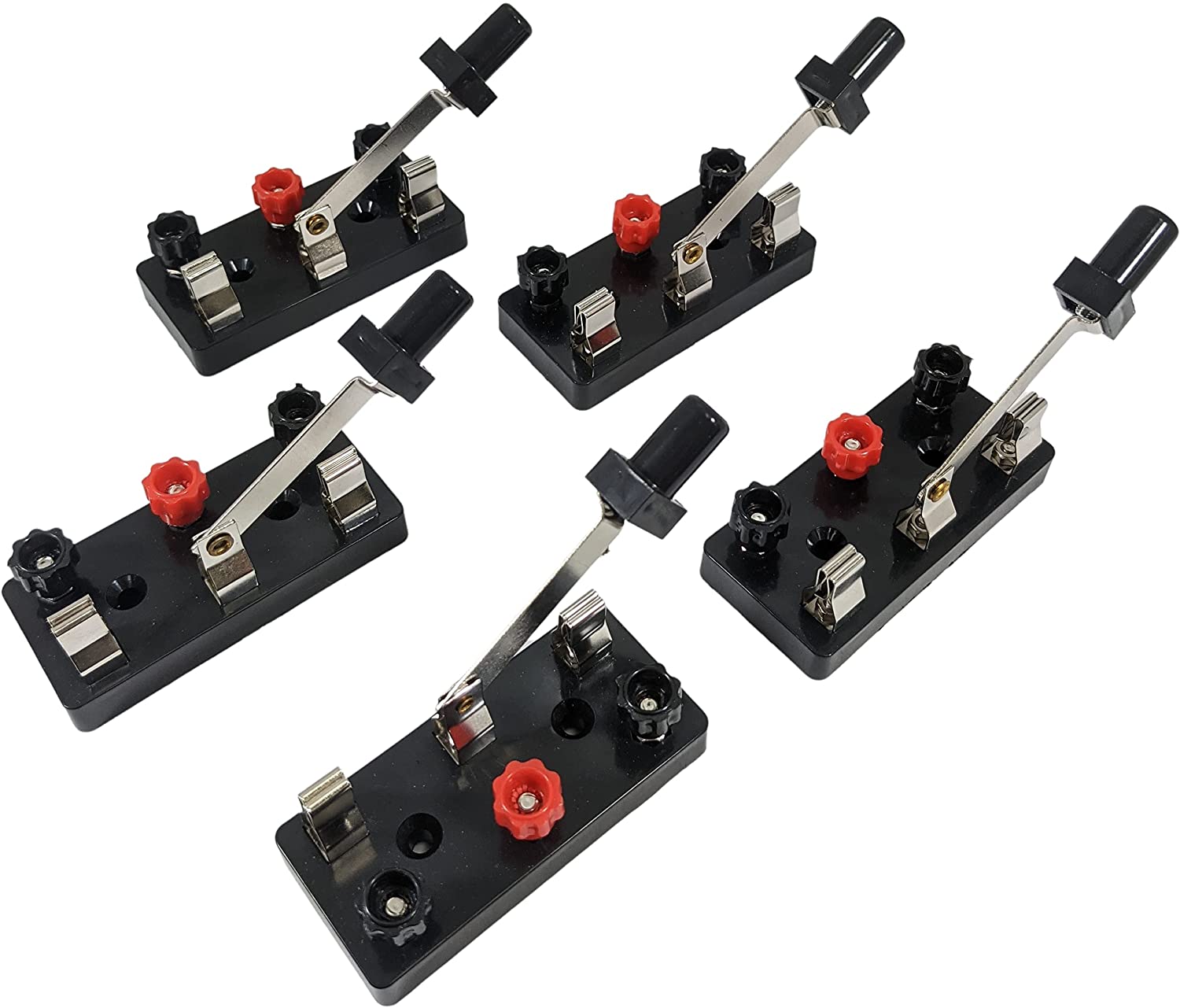
Knife Switch, SPST
Product Code: SPST

Knife switch, single pole single throw, with screw type binding posts.

and 2 screw holes for mounting on a board. Good for experiments and science projects.

High quality, deluxe version.

Screw type binding posts may be both black or one black, one red.

Weight = 25g

Measurements:
Base Alone: Length = 74mm  Width = 35mm  Height = 10mm

Length with Pole = 98mm   Height with Pole = 33mm


Knife Switch, SPDT
Product Code: SPDT

Knife switch, single pole double throw, with screw type binding posts.

and 2 screw holes for mounting on a board.

Good for experiments and science projects. High quality, Deluxe version.

Weight = 41.5g

Measurements:
Base Alone:  Length = 74mm  Width = 35mm  Height = 10mm

Length with Pole = 105mm   Height with Pole = 29mm


Knife Switch, DPST
Product Code: DPST

This Knife Switch is double pole, single throw with screw type binding posts.

3 screw holes for mounting on a board. Good for experiments and science projects.

High quality, Deluxe version.

Weight = 46g

Measurements:
Base Alone:  Length = 74mm  Width = 50mm   Height= 10mm

Length with Pole = 100mm   Height with Pole = 29mm


Knife Switch, DPDT
Product Code: DPDT

This Knife Switch is double pole, double throw with screw type binding posts.

3 screw holes for mounting on a board. Good for experiments and science projects.

High quality, Deluxe version.

Weight = 73g

Measurements:
Base Alone:  Length = 74mm  Width = 52mm  Height = 10mm

Length with Pole = 106mm  Height with Pole 29mm

Simple Switch (Knife Switch)
Product Code: KSWITCH

This small size simple switch is used by students to make electrical circuits.

This quality knife switch is perfect for science projects and electronic experimentation.

With its pre-drilled holes, it can easily be mounted on any wooden surface or project board.

Because of the open structure of the switch, you can visually determine if the circuit is closed or open.

Weight = 9.3g

Measurements:
Base Alone:  Length = 36mm  Width = 24mm  Height = 7mm

Length with Pole = 50mm   Height with Pole = 23mm

electric fuse

electric fuse

We are pleased to have you visit our pages on social networking sites,

where we publish exclusive offers on our website.

Our Facebook page here .

Our Twitter account is here .
Posted on Leave a comment

Electrical Contactor Connection and Wiring 1

Electrical Contactor Connection and Wiring

Hey, in this article we are going to see proper electrical contactor connection and wiring diagram for normal operation, star-delta starter, motor control, light control, etc. Also, we will discuss the internal circuit diagram of the contactor used for power control.

What is Electrical Contactor?

In simple words, Electrical Contactor is an electrically operated switch whose main function is to connect or disconnect the load from the power source. Basically, the contactor work as a medium when we control a high voltage, high current power circuit by a low voltage, low current control circuit.
Contactor Symbol:

Electrical Contactor Connection and Wiring

Contactor Terminals and Contacts

Before you going to do a connection for a contactor you must know about its terminals and contacts. Basically, a contactor has two types of contacts – 1. Main or Power Contacts and 2. Auxiliary Contacts
In the below figure, you can see there is a total of 16 terminals in the contactor.

A1 and A2 are magnetic coil terminals.
L1, L2, and L3 are the incoming terminals of the main contact which are to be connected to the main power supply.
T1, T2, and T3 are the outgoing terminals of the main contact which are to be connected to the load.
Here two NC and two NO auxiliary contacts are available. Each of them has two terminals.

Contactor Connection Procedure

1. Generally the magnetic coil of a contactor is designed to operate at a low voltage such as 230V AC, 110V AC, 24V DC, etc. So provide the power supply to the magnetic coil as per requirement.
2. Connect the main power supply terminal with the incoming terminals of the contactor.
3. Connect the load with the outgoing terminals of the contactor.

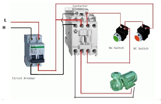
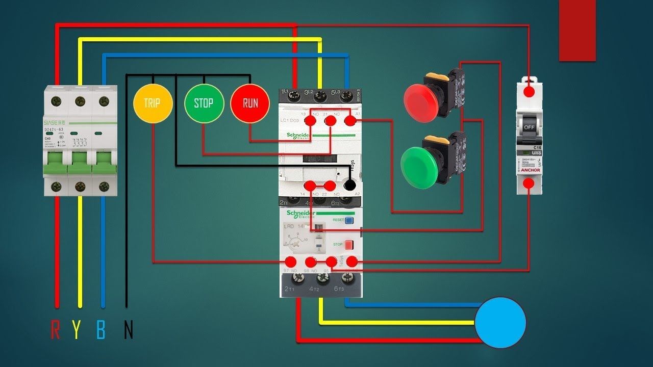
Contactor connection with Push Button Switch

Now we are going to see, how to connect the push button switch with a contactor. Here the connection diagram in the below figure.

You can see here, two push button switches are used. NC push button(green colour) switch is used to turn off the contactor whereas the NO push button(Red colour) switch is used to turn on the contactor.
These pushbutton switches break or make the contacts only when we press the button. Once we release the button its contacts also come back to their old position. So the magnetic coil of the contactor is also connected through the NO auxiliary contacts. So the contactor will be turned on once we press the switch and remain On even when we release the NO push button. The contactor will remain turned on until we press the NC push button.

Contactor connection with Indication Lamps

Now, let’s go to know how to connect indication lamps with a contactor to give indications whether it is in ON condition or OFF condition. See the below diagram.

Here we have taken two indication lamps – Red for ON, Green for OFF.
You can see the Red indication lamp is connected through the NO auxiliary contact. So when the contactor turning on it will glow. On the other hand, the green indication lamp is connected through the NC auxiliary contact. So when the contactor is in OFF condition, this lamp will glow. Once the contactor is turned ON it will off and the red colour lamp will glow.

Contactor Connection with Thermal Overload Relay

Thermal Overload Relay is mainly used to give protection against overload fault. So thermal overload relay used with electrical contactor when we designed DOL Starter, Star Delta Starter, etc.
Here you can see the connection of thermal overload relay with a contactor in the DOL Starter Circuit.

كيفية توصيل القواطع الكهربائية المنزلية

lightning
We are pleased to have you visit our pages on social networking sites, where we publish exclusive offers on our website.

 Facebook page here.

Twitter account is here.

Posted on Leave a comment

Electrical Circuit Breaker

Electrical Circuit Breaker |

Operation and Types of Circuit Breaker

Electrical Circuit BreakerWhat is Circuit Breaker?

An electrical circuit breaker is a switching device which can be

operated manually and automatically for controlling

and protecting an electrical power system.

As the modern power system deals with huge currents,

special attention should be given during designing of a circuit breaker to ensure it is able to safely

interrupt the arc produced during the closing of a circuit breaker.

This was the basic definition of circuit breaker.

Introduction to Circuit Breaker

The modern power system deals with huge power network and huge numbers of associated electrical equipment.

During a short circuit fault or any other type of electrical fault (such as electric cable faults),

a high fault current will flow through this equipment as well as the power network itself.

This high current may damage the equipment and networks permanently.

For saving these pieces of equipment and the power networks,

the fault current should be cleared from the system as quickly as possible.

Again after the fault is removed,

the system must come to its normal working condition as soon

as possible for supplying reliable quality power to the receiving ends.

In addition to that for proper controlling of the power system,

different switching operations are required to be performed.

So for timely disconnecting and reconnecting different parts of power system network for protection and control,

there must be some special type of switching devices which can be operated safely under huge current carrying condition.

During the interruption of large current,

there would be large arcing in between switching contacts,

so care should be taken to quench these arcs in circuit breaker in a safe manner.

The circuit breaker is the special device which does all the required switching operations during current carrying condition.

This was the basic introduction to circuit breaker.

Working Principle of Circuit Breaker

The circuit breaker mainly consists of fixed contacts and moving contacts.

In normal “ON” condition of the circuit breaker,

these two contacts are physically connected to each other due to applied mechanical pressure on the moving contacts.

There is an arrangement stored potential energy in the operating mechanism of circuit breaker

which is released if the switching signal is given to the breaker.

The potential energy can be stored in the circuit breaker by different ways like by deforming metal spring,

by compressed air, or by hydraulic pressure. But whatever the source of potential energy,

it must be released during operation.

The release of potential energy makes the sliding of the moving contact in a speedy manner.

All circuit breaker have operating coils (tripping coils and close coil),
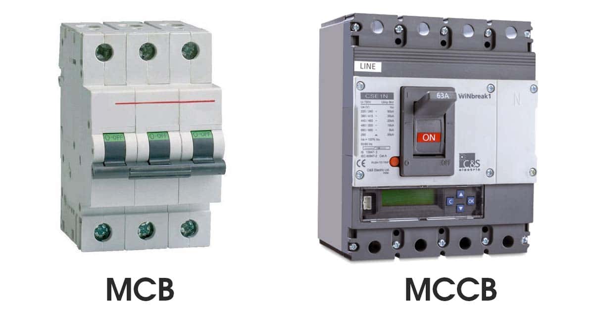
whenever these coils are energized by switching pulse,

and the plunger inside them displaced.

This operating coil plunger is typically attached to the operating mechanism of circuit breaker,

as a result the mechanically stored potential energy in the breaker mechanism is released in forms of kinetic energy,

which makes the moving contact to move as these moving contacts mechanically

attached through a gear lever arrangement with the operating mechanism.

After a cycle of operation of circuit breaker the total stored energy is released

and hence the potential energy again stored in the operating mechanism of the circuit breaker

using spring charging motor or air compressor or by any other means.

Till now we have discussed mechanical working principle of circuit breaker.

But there are electrical characteristics of a circuit breaker which also should be considered in

this discussion of the operation of the circuit breaker.

Let’s have a discussion on electrical principle of circuit breaker.

The circuit breaker has to carry large rated or fault power.

Due to this large power, there is always dangerously high arcing between moving contacts

and fixed contact during operation of the circuit breaker.

Again as we discussed earlier the arc in circuit breaker can be quenching safely

if the dielectric strength between the current carrying contacts of circuit breaker

increases rapidly during every current zero crossing of the alternating current.

The dielectric strength of the media in between contacts can be increased in numbers of ways,

like by compressing the ionized arcing media since compressing accelerates the deionization process of the media,

by cooling the arcing media since cooling increase the resistance of arcing path or by replacing the ionized

arcing media with fresh gasses. Hence some arc quenching processes should be involved in the operation of the circuit breaker.

Although circuit breakers perform their function independently and without supervision,

there are also remote control circuit breakers which can be operated on demand at a distance.

Types of Circuit Breaker

According different criteria there are different types of circuit breaker.

According to their arc quenching media the circuit breaker can be categorized as:

  1. Oil circuit breaker.
  2. Air circuit breaker.
  3. SF6 circuit breaker.
  4. Vacuum circuit breaker.

According to their services the circuit breaker can be categorized as:

  1. Outdoor circuit breaker.
  2. Indoor breaker.

According to the operating mechanism of circuit breaker they can be categorized as:

  1. Spring operated circuit breaker.
  2. Pneumatic circuit breaker.
  3. Hydraulic circuit breaker.

According to the voltage level of installation types of circuit breaker are referred as-

  1. High voltage circuit breaker.
  2. Medium voltage circuit breaker.
  3. Low voltage circuit breaker.

ما هو مرحل الحمل الزائد (الاوفر لود): أنواعه وتطبيقاته

يسعدنا زيارتكم صفحاتنا على مواقع التواصل الاجتماعي حيث نقوم بنشر عروض حصرية على موقعنا الالكتروني.

صفحتنا علي الفيسبوك هنا.

حسابنا على تويتر هنا.

Posted on Leave a comment

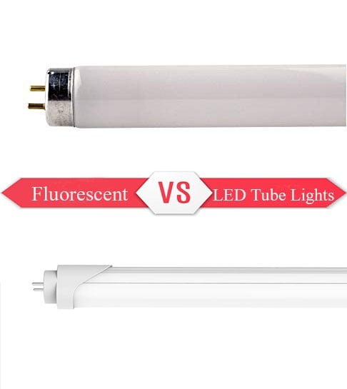
LED vs Fluorescent Tubes

LED vs Fluorescent Tubes

LED vs Fluorescent TubesFluorescent lighting has been around for over 100 years.
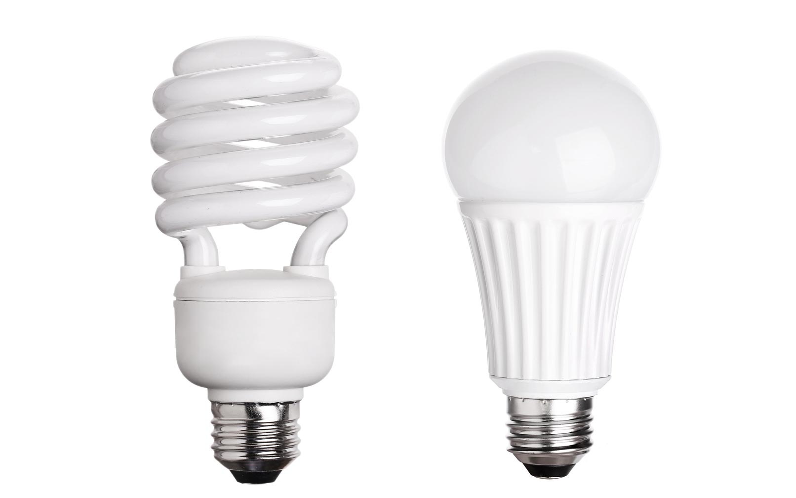
When compared to incandescent lighting, florescent lights have long been touted as energy-efficient

, longer-lasting, and a great way to illuminate large spaces.

However, as the Light-Emitting Diode (LED) continues to evolve,

many experts and business owners have found sound reasoning in switching to this modern lighting.

Below, our experts here at Action Services Group help explain why it may

be time for you to invest in LED technology in our latest blog LED vs. Fluorescent Tubes.


What Is A Linear or Tube Fluorescent Light?

Fluorescent lights are part of the High-Intensity Discharge (HID) family.
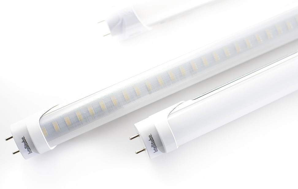
As such, they produce light through the use of a type of gas-discharge.

Fluorescent lights typically consist of a glass outer tube that encases a thinner arc

tube that is internally treated with a fluorescent coating. Within this arc tube, an inert mercury gas is contained.

When an electrical charge is supplied to the arc tube, it excites the mercury gas and releases ultraviolet (UV) radiation.

When the UV radiation interacts with the fluorescent coating, it creates light.

Standard linear fluorescent lights are typically available in tubes that measure 48- to 84 inches in length.


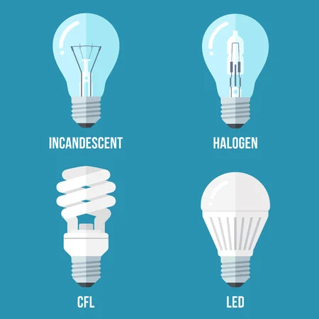
CFL: A Compact Variant


While modern technology has created subsets of fluorescent lighting,

it is not uncommon for users to mistake CFLs for linear fluorescent lights.

CFL, which stands for Compact Fluorescent Light, are smaller versions of the standard fluorescent lighting we are talking about.

While CFLs are available in linear shapes, they are more commonly coiled in appearance. 

LED vs. Fluorescent Tubes Cost Savings

When it comes to retrofitting an older system or installing a new one, cost savings is often one of the biggest factors.

When talking about lighting installations, the overall cost impacts

need to take into account the overall energy consumption costs as well as those related to maintenance.

Let’s take a closer look at how LED vs. fluorescent tubes stack up when it comes to cost savings.

Energy Savings

We have noted that florescent lights are considered more efficient than incandescent bulbs.

However, nothing beats the energy savings when it comes to an LED. Fluorescent lights are omnidirectional.

This means they emit light a full 360 degrees around the bulb itself.

LED lights are one-directional, meaning they emit light in a focused 110-degree area.

But what does this mean to you? Fluorescent lights will rely on the use of a reflecting plate.

This causes an immediate reduction in lighting quality by 15%.

In addition to this, a fluorescent bulb relies on heat to produce the UV radiation from mercury gases.

When light is emitted in an omnidirectional manner, it means that heat escapes from all sides as well.

This results in more power being needed to maintain the same level of lighting.

LEDs, on the other hand, do not require any heat to produce light and emit very little of it while in use.

(Want an additional cost savings? By reducing the heat emitted by your lighting sources,

you can also expect to decrease your air-conditioning use!) Additionally, fluorescent lights need time to warm up.

While today’s technology has led to the development of florescent bulbs that warm up rapidly,

they still suffer from a delay in reaching maximum illumination.

LEDs reach full illumination immediately,

meaning energy is not wasted on bringing the lamp up to the required temperature

to produce mercury gas-based UV radiation.

Because lighting accounts for almost 40% of your entire power bill,

every second you can cut down on powering light fixtures means money you save.

Based on the direction, loss of heat, and reflection reductions –

LED lights provide almost 70% more light when supplied with the same amount of energy as a fluorescent tube.

Maintenance Savings

When it comes to linear LED vs linear fluorescent lamp maintenance, LEDs again take the lead.

Fluorescent tubes typically last between 3 and 5 years.

However, because the internal ballast is rather fragile,

should that component be damaged in any way, the lamp will no longer work. Should the ballast not be damaged,

a fluorescent tube shows signs of light degradation as it nears the end of its lifespan.

As the tube begins to die, the ends will blacken and the light will flicker,

which can cause health issues for those exposed to it.

(Headaches, migraines, eye issues, and epileptic seizures are just some of the potential concerns.)

LEDs, however, last between 50,000 and 100,000 hours.

Made of more robust materials and a simple solid-state diode assembly,

LEDs are extremely durable and can withstand much more abuse and vibration than fluorescent lamps can.

In fact, some linear LED manufacturers are so confident in their durability,

they even offer a 10-year warranty on their lamps.


At the end of the day, whether you damage the ballast of a fluorescent tube or not,

you will need to replace it 3.5 times more often than you will need to replace an LED.


LED vs. Fluorescent Tubes Quality of Light

When it comes to the expected quality of LED vs fluorescent tubes, experts again recommend LEDs for all our lighting needs.

Why?

Performance

We have already discussed how robust an LED light is when compared to a fluorescent lamp.

However, the spectrum of light that is available from LEDs far exceeds what is available through its fluorescent counterpart.

Because of its inherent design, the entire color wheel is represented through the diodes used in an LED.

This allows it to produce all shades of color, including even the slightest variations between bright white and natural light.

Fluorescent lighting, however, utilizes the blue, green and red color wheel.

This gives the lighting an extremely artificial feel and has been known

to increase the likelihood of headaches and eye problems. Furthermore,

it can skew the colors of objects under them.

Depending on what your business does, this can be an issue.

Lumens

Fluorescent lights produce between 50 and 100 lumens per watt.

By comparison, LEDs can produce roughly 130 lumens per watt.

For example, a T5HO Commercial LED tube light uses only 25 watts to produce an output of 3334 lumens.

In other words, LEDs require fewer watts to produce a brighter light.

كيفية توصيل القواطع الكهربائية المنزلية

lightning
We are pleased to have you visit our pages on social networking sites, where we publish exclusive offers on our website.

 Facebook page here.

Twitter account is here.