Posted on Leave a comment

Ex de lighting fixtures and floodlights with LED technology 2022

Ex de lighting fixtures and floodlights with LED technology

1. Introduction It’s appropriate to clarify some beliefs about LED lighting fixtures and,

more specifically, about their use in the…
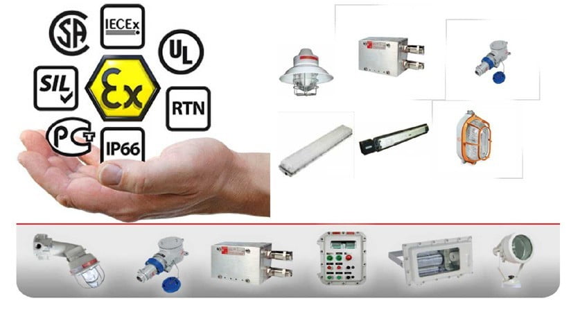
Ex de lighting fixtures

It’s appropriate to clarify some beliefs about LED lighting fixtures and, more specifically,

about their use in the segment of environments with a risk of explosion and fire:

as men progressed in a continuous research of new technologies through by the technique of breaking stones

for tools and the creation of energy by exploiting the natural flow of the rivers, in the same way Cortem is pursuing

this philosophy approaching new technologies and adapting them to specific projects of research and development

without being fossilized in the past.

First, we analyzed carefully what the LED market was offering us by comparing the production quality of each manufacturer.

The analysis has led to choose products that could give us the appropriate functional guarantees

about the very low “infant mortality” of LED and, therefore, we continued with the

engineering of new lighting fixtures designed depending on application parameters guaranteed by the producers themselves.

These parameters must be appropriate to the right temperature dissipation for an adequate and sustainable use

in terms of the warranty for the customer.In fact, as you can see from the following photos,

the new series of LED lighting fixtures and floodlights designed by Cortem have nothing in common with

lighting fixtures and floodlights for  discharge lamps.

The old “enclosures” are not suitable to be used as a support for LED and do not lend themselves

to dissipate the temperature generated, compromising the proper functioning and durability.

Unfortunately, the “adaptation” and the transformation of old Ex lighting fixtures to new LED lighting fixtures

are very widespread practices in the market. This leads to poor performance and limited benefits in

terms of energy and cost savings for the end user.

The use of appropriate LED lighting fixtures allows to obtain numerous advantages.

Consider that a discharge lamp of 400W can be replaced with LEDs with a power of 160 W,

with an energy saving of about 60%. Furthermore, current Cortem LED lighting fixtures,

in addition to being not much more expensive to lighting fixtures for discharge lamps,

are plenty amortized over time due to the lower costs of maintenance.

The frequency of maintenance, in fact, decreased by 1.7 compared to the activity required for the re-establishment

of a discharge lamps lighting fixtures. It’s well known that a discharge lamp has an average life ranging from 3.000 to 10.000 hours

and then stops working, while LEDs  have an average life of 50.000-70.000 hours and

continues to work, only losing luminous efficiency.

The use of LEDs in the new range of Cortem products allowed us also to get floodlights with T5 class temperature,

much lower than the class temperature of the floodlights with discharge lamps (T2 / T3).

They can therefore be installed in hazardous areas where, until now, it was unthinkable to install a floodlight.

One of the main problems encountered, in order to ensure the safety in the workplace,

is to ensure an adequate level of illumination of the plants. In particular,

the characteristics of electrical equipment installed in areas with danger of explosion are designed with even

greater attention to get good illumination and reduction of risk conditions.

About 80% of all our sensory impressions are of optical nature and they need of light as a vehicle of information.

Good lighting, therefore, not only facilitates the vision and the recognition, but it greatly reduces the danger of accidents.

The devices that are installed in hazardous areas must therefore ensure, in addition to explosion protection,

the proper lighting required for the execution of all work operations in conditions of maximum security and must

have other characteristics, such as the reduced need for maintenance in order to minimize

risks associated with the equipment operation.

The LED is a light-emitting diode, otherwise, an optoelectronic device that uses the optical properties of

some semiconductor materials to produce photons through the phenomenon of spontaneous emission.

The first LED was developed in 1962 and, from that moment on, the technology has made great strides.

Today we have components that can be effectively used for industrial lighting.The main advantages of using

LEDs in lighting fixtures can be summarized as follows:

  • Reduced dimensions and lightweight than conventional lighting fixtures of equal power
  • High efficiency and energy savings
  • Long life (approximately 100,000 hours) with consequent reduction of maintenance costs
  • Resistance to vibration
  • No UV emission
  • Instant restrike
  • Excellent performance in harsh application
  • Anti-light pollution

In the specific case of the use of such components in the construction of lighting equipment used in classified areas,

the main advantage lies surely in the long duration that, in addition to being convenient in economic terms,

means a smaller number of maintenance interventions (lamping) on lighting equipment.

This is very positive in terms of safety, because, as you know, every intervention on equipment installed

in areas with risk of explosion increases the risk level of the system.

Another advantage of LED is that, unlike other sources of artificial lighting, once reached its limit of life,

not shut down abruptly, but continues to operate with a luminous flux reduction. This is synonymous of safety,

especially in those places of the plant where the lighting is fundamental to prevent accidents or injuries.

2.1 The light spectrum

The light spectrum of white LEDs of the latest generation, such as those used for the realization of our LED range,

is about as close to sun light spectrum. In the diagrams below, you can appreciate the differences between

the spectrum of sunlight and of other light sources, such as fluorescent lamps, discharge lamps and white LEDs.

For our LED products, we use only Cree LEDs with maximum efficiency,

in order to obtain the best light quality and the maximum lumen output.

All lighting fixtures have a CRI (Color rendering index) > 70 and a standard light color cool white 5700° K.

For special needs, can be requested a different color temperature.

After analyzing the characteristics associated with the use of LED technology,

let’s see the features of LED lighting fixtures that allow their use in classified areas for the presence of an explosive atmosphere.

For use in areas with danger of explosion is obviously necessary that the lighting equipment are designed,

built and certified according to technical regulations implemented by the ATEX Directive 94/9/ EC

and by the new ATEX Directive 2014/34/EU entered in force on March, 30th 2014. It will repeal,

with effect from April 20th 2016, the ATEX Directive 94/9/EC. The protection methods that can be used are the following:

  • Ex “d” explosion-proof: the philosophy of this method is based on the consideration that it’s not possible to prevent a gas to spread everywhere. The main advantage of this method of protection is that the electrical elements installed inside the lighting fixture, constructed to contain any explosion, are common components easy to find.
  • Ex “e” increased safety: the purpose of this method is to ensure security measures to prevent the formation of arcs or sparks. The main advantage of this method of protection is its simplicity of construction and, above all, applications. One of the disadvantages is the fact that the components, besides not being easy to find on the market, must be individually protected.
  • Ex “m” encapsulated: the purpose of this method is to prevent an explosive atmosphere may come in contact with ignition sources by encapsulating the equipment.

Cortem has designed and manufactured a full range of lighting equipment and floodlights that use the latest LED technology generation.

The LED technology in the coming years, will certainly replace other sources of

artificial lighting designed to obsolescence because of operating costs, environmental problems and ease of use.

4.1 EWL series lighting fixtures and floodlights – High Bay

EWL series consists of three models of High-bay lighting fixtures, EWL 70, EWL-80, EWL-100,

and three models of floodlights, EWL-70/ .., EWL-80/…, EWL-100/… with different optics:

Narrow (10°), Medium (20°) and Wide (40°).

Through the use of optics with different angles, you can get the optimal light beam in well-defined areas.

This allows maximum versatility of use, ensuring the proper illumination of the workplace.

A new feature for these lighting fixtures is the possibility to be powered at 24 VDC.

For the first time in the lighting history of areas with danger of explosion,

it’s available a lighting system with a lighting efficiency comparable to that obtainable with discharge lamps,

powered directly with alternative systems such as wind turbines, solar panels, battery systems.

As we said in the introduction, the LED lighting fixtures must be designed and constructed specifically.

The construction of bodies in aluminum alloy, designed with elements of heat dissipation,

is the key to obtain an efficient and long lasting system.

The housing of the feeder must be correctly calculated in terms of volume to allow easier heat dissipation.

In the picture below you can appreciate the thermo-graphic survey.

The finned body, made of aluminum alloy, acts as a heat sink for the LED plate mounted directly inside,

on the body of the lighting fixture allowing it to dissipate more quickly and effectively

the heating generated by the operation of the LEDs themselves.The design of the lamp body,

in addition to being functional to the duration of the system,

has allowed obtaining equipment with high luminous efficiency in relation to the maximum surface temperature.

This is a very important factor for the installation of lighting fixtures in places of danger,

containing gas or powders at low ignition temperature.

A further saving is obtained thanks to the fact that, while discharge lamps requires a preheating time for their complete ignition and,

for this reason, the lights of a plant are lighted up 24 hours, LEDs have an Instant Restrike.

A LED system can be effectively connected to automatic ignition system in case of low light,

allowing the use only for periods actually needed and, consequently, with a further saving of energy costs.

LED technology allows also adjusting the light output according to the real needs of the room to be lighted (dimming).

EWL series features with ‘Ex de’ method of protection for Gas and ‘Ex t’ for Dusts.

This choice allows powering the equipment through a ‘Ex e’ cable gland and without the need to perform sealings on field.

A tapped hole opposite to the entrance of the cable, allows the connection through wiring.

It’s now available a new version of the EWL-80 series, the EWL-801, both in lighting fixture and floodlight version.

The EWL-801 makes it possible to obtain, with the same size but with a power consumption of 110W,

a lumen output almost twice respect to EWL-80, 10100 lm compared to 6050 lm,

and a maximum light intensity much higher: 4330 cd for the lighting fixture version and 118670 cd (EWL-801/10),

51680 (EWL-801/20) and 20900 (EWL-801/40) for the version with optical concentrating of the light beam.

The series EWL has been certified and complies with the requirements of the following standards:

• EN/IEC 60079-0 Electrical apparatus for explosive atmospheres due to the presence of gas – Part 0:

General requirements;

• EN/IEC 60079-1 Explosive atmospheres – Part 1: Equipment protected by flameproof enclosures “d”;

• EN/IEC 60079-7 Explosive atmospheres – Part 7: Equipment protection by increased safety “e”;

• EN/IEC 60079-31 Explosive atmospheres – Part 31: Equipment with protection by enclosure “t” for use in presence of combustible dust.

It was also subjected to the tests required for the photo-biological risk assessment regulated by IEC/EN 62471 standards.

These tests measure the amount of emissions of UV, blue light and infrared radiation (IR),

which may cause damage to the skin and eyes (retina and cornea) operators.

The lighting fixtures and floodlights EWL series are EXEMPT from the photo-biological risk.4.2 EVL series lighting fixtures

The new LED compact lighting fixtures EVL series features Multichip LED formed from a matrix of LEDs

connected together and covered with a layer of diffused phosphorus. This technology allows obtaining high

values of lumen output and the installation at low heights, without the risk of disturbing the operator.

The EVL series consists of three lighting fixtures sizes: EVL-60, EVL-70 and EVL-80.

It represents the LED alternative for all those areas in which it was usual to use lighting fixtures with discharge

lamps of low and medium power up to 400W.

It’s equipped with fins that act as a heat sink and the electrical connection is easier thanks to a ‘Ex e’ terminal box,

which allows the entry with a ‘Ex e’ cable gland (no barrier). In addition, a tapped opposed hole allows the loop in/loop out facility.

In the following table, we can compare the power of EVL series lighting fixtures and of traditional lamps.

You will immediately appreciate the savings you can get.

4.3 EVE-L series lighting fixtures with LED remote phosphor technology – Low Bay

EVE-L series Cortem lighting fixtures are designed to provide an optimal replacement to the conventional incandescent lamps from

50W up to 200W. It’s available in two sizes: EVE-5050 end EVE-5060.

The peculiarity of these new lighting fixtures consists in the use of the LED Remote Phosphor Technology

on explosion-proof lighting fixtures.

This represent an absolute evolution in the world of LEDs and an important step forward in terms of energy efficiency,

lighting efficiency and chromatic yield quality.

The LED Remote Phosphor Technology is based on a yellow semi-spherical light diffuser that, when the lighting fixture is on,

absorbs the light produced by the internal LEDs and releases white light.

The EVE series allows to replace the lighting fixtures which use incandescent and energy-saving lamps with a

long lasting light source that ensures a better efficiency and an equal brightness comfort.

4.4 FLF-…L and FLFE-…L series lighting fixtures

Lighting fixtures for LED tubes FLF-…L (Ex d) and FLFE-…L (Ex de) series have two low copper content aluminium

heads with G13 lamp holder, a tempered borosilicate glass tube, that is resistant to changes in heat,

and a white painted aluminium reflector.

Both the series are available with one tube or with two tubes.

FLFE-…L series, in ‘Ex de’ way of protection, features an

“Ex e” terminal board housing that allows entry to the fixtures with a cable gland with an

“Ex” seal (normal), while FLF-…L series, in ‘Ex d’ way of protection, as specified in the appropriate installation standard

(EN/IEC 60079-14), the entry to the fixture must be through an Ex “barrier” cable gland (sealed)

or, in the case of a conduit system, with an EYS, EZS series sealing fittings.

The use of LED tubes, which have the same dimensions of fluorescent ones, allows to obtain economy in operating costs,

due to their long life, high-efficiency lighting, thanks to directional light,

and LED light quality with a color rendering index of 85 (CRI).Furthermore,

LEDs do not ionize the particles of air around the lamp and do not attract, then, the dust particles suspended in the air.

The round cross section of the lighting fixtures provides a better “Cx” coefficient with less resistance

to the wind and less accumulation of dust. FLFE series has been designed to facilitate and speed up maintenance operations.

As the electrical components are housed on a frame with guides,

re-lamping is quick and efficient. Furthermore,

the different types of mounting attacks and the absence of sealing fittings make the lighting fixtures particularly well performing.

4.5 EXEL-L series lighting fixtures (Work in progress)

EXEL-L series increased safety lighting fixtures for LEDs tubes are suitable to be installed in hazardous areas

1, 2, 21 and 22 where a high degree of protection and resistance against corrosion is required such as

in chemical and petrochemical plants, off-shore and on-shore plants, processing areas in food industries

etc… EXEL-L series is polyester made, with ‘Ex e-mb’ method of protection for LED tubes with remote

phosphor diffusers to reduce glare.

The through wiring double ended makes installation on field easier and

faster than normal lighting fixtures.

The transparent cover is clipped into place on both sides of the fixture body with 8

clips on the 785 mm model and 14 clips on the 1370 mm unit.

This ensures excellent protection against dust and water over time despite of degradation caused by ageing.

4.6 EVML-50 series lighting fixtures – Low Bay (Work in progress, end 2014)EVML-50 lighting fixtures,

in the design development phase,

have been conceived to offer a Low Bay lighting fixture that could replace incandescent equivalents at lower costs.

They are suitable for the illumination of small areas in which it’s necessary to limit the obstruction such as tunnels,

passages, corridors, stairways, perimeter walls and command and control cabins.

The EVML-50 series features the ‘Ex e mb’ method of protection:

the electronic board and the LEDs are protected with silicone of high transparency.

4.7 EVOLED series lighting fixtures (Work in progress)

The new EVOLED series lighting fixtures are designed for the internal lighting of boilers,

tanks, evaporators, silos, storage tanks, pipelines or other containers present in all those areas where hazardous vapors

, gases, dust or other fuels are present during the normal operation of a plant.

In addition to ensuring low power consumption and light efficiency,

the lighting fixture is provided with an external switch for an easy switching on and off after installation.

4.8 SLED series floodlights (Work in progress)SLED series rectangular floodlights, in the design development phase,

are equipped with “Wide area” optics for the symmetric and asymmetric illumination of industrial areas,

in general, and of hazardous areas.

Designed with ‘Ex m’ method of protection (encapsulation), SLED series floodlights are characterized by size,

weight and power consumption much lower than the floodlights fitted with conventional discharge lamps.

Safety is essential for workplaces and, especially in areas with potentially explosive atmospheres, the risks are very high.

Any system, therefore, that allows to reduce the level of risk is always well accepted.

Furthermore, if there are savings in money and energy, then the advantage is total.

The LED lighting in industrial sector is a path just started, but it’s definitely the

way to be followed to ensure a future of light and safety.

We summarize here, in conclusion, the main advantages that presents the range of Cortem’s

LED products with which we set ourselves several steps ahead in terms of technology against competitors:

  1. Energy saving with maximum efficiency, more light and less consumption.
  2. Longer life than conventional bulbs and, thus, reducing of maintenance costs.
  3. Savings of plant costs, lower costs to bring energy to the lamp.
  4. Directional light and superior quality allow a better identification of the colors of illuminated objects. Safety in the workplace.
  5. Use in lighting systems at low voltage (24Vdc).
  6. Resistance in the ON / OFF cycles.
  7. No Light Out for the security in the workplace.
  8. Resistance of the components to the electrical and mechanical stresses.
  9. Less weight, less volume, easier handling.
  10. Excellent heat dissipation for longer life of the LED.
  11. Possible electronic control of the light output (dimming).
  12. Respect for the environment, compliance with the standard anti-light pollution.
  13. Excellent performance in extreme climates.
  14. Immediate availability of the maximum light output power.
  15. Very low mortality of LEDs.
  16. Lower temperature classes.
  17. ‘Ex de’ method of protection allows the entry of the cable without realizing any conduit system with sealing.
  18. Possibility of replacing the LED plate with a more advanced technology (Future Proof).
  19. In the remote case of failure of one of the LEDs, the Ex safety remains unchanged.
  20. Multifunctional. From lighting fixtures to floodlight with the sole plate replacement.
  21. Guaranteed 50,000 hours (25° C ambient temperature).
  22. Suitable for classified areas as IIB and IIC.
  23. 100% recyclable.
  24. No flickering.
  25. Absence of hazardous substances such as the mercury for fluorescent lamps.

Electrical transformers

We are pleased to have you visit our pages on social networking sites,

where we publish exclusive offers on our website.

Our Facebook page here .

Our Twitter account is here .
Posted on Leave a comment

Electrical Contactor Connection and Wiring 1

Electrical Contactor Connection and Wiring

Hey, in this article we are going to see proper electrical contactor connection and wiring diagram for normal operation, star-delta starter, motor control, light control, etc. Also, we will discuss the internal circuit diagram of the contactor used for power control.

What is Electrical Contactor?

In simple words, Electrical Contactor is an electrically operated switch whose main function is to connect or disconnect the load from the power source. Basically, the contactor work as a medium when we control a high voltage, high current power circuit by a low voltage, low current control circuit.
Contactor Symbol:

Electrical Contactor Connection and Wiring

Contactor Terminals and Contacts

Before you going to do a connection for a contactor you must know about its terminals and contacts. Basically, a contactor has two types of contacts – 1. Main or Power Contacts and 2. Auxiliary Contacts
In the below figure, you can see there is a total of 16 terminals in the contactor.

A1 and A2 are magnetic coil terminals.
L1, L2, and L3 are the incoming terminals of the main contact which are to be connected to the main power supply.
T1, T2, and T3 are the outgoing terminals of the main contact which are to be connected to the load.
Here two NC and two NO auxiliary contacts are available. Each of them has two terminals.

Contactor Connection Procedure

1. Generally the magnetic coil of a contactor is designed to operate at a low voltage such as 230V AC, 110V AC, 24V DC, etc. So provide the power supply to the magnetic coil as per requirement.
2. Connect the main power supply terminal with the incoming terminals of the contactor.
3. Connect the load with the outgoing terminals of the contactor.

Contactor connection with Push Button Switch

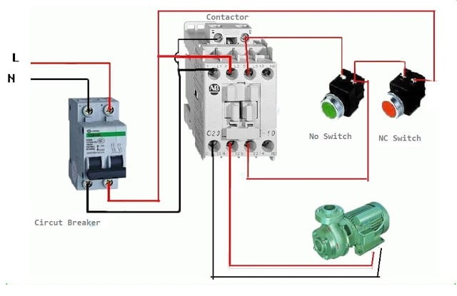
Now we are going to see, how to connect the push button switch with a contactor. Here the connection diagram in the below figure.

You can see here, two push button switches are used. NC push button(green colour) switch is used to turn off the contactor whereas the NO push button(Red colour) switch is used to turn on the contactor.
These pushbutton switches break or make the contacts only when we press the button. Once we release the button its contacts also come back to their old position. So the magnetic coil of the contactor is also connected through the NO auxiliary contacts. So the contactor will be turned on once we press the switch and remain On even when we release the NO push button. The contactor will remain turned on until we press the NC push button.

Contactor connection with Indication Lamps

Now, let’s go to know how to connect indication lamps with a contactor to give indications whether it is in ON condition or OFF condition. See the below diagram.

Here we have taken two indication lamps – Red for ON, Green for OFF.
You can see the Red indication lamp is connected through the NO auxiliary contact. So when the contactor turning on it will glow. On the other hand, the green indication lamp is connected through the NC auxiliary contact. So when the contactor is in OFF condition, this lamp will glow. Once the contactor is turned ON it will off and the red colour lamp will glow.

Contactor Connection with Thermal Overload Relay

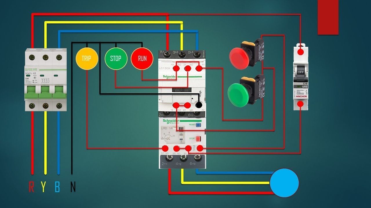
Thermal Overload Relay is mainly used to give protection against overload fault. So thermal overload relay used with electrical contactor when we designed DOL Starter, Star Delta Starter, etc.
Here you can see the connection of thermal overload relay with a contactor in the DOL Starter Circuit.

كيفية توصيل القواطع الكهربائية المنزلية

lightning
We are pleased to have you visit our pages on social networking sites, where we publish exclusive offers on our website.

 Facebook page here.

Twitter account is here.

Posted on Leave a comment

How to Install Electrical Wiring System Properly?

How to Install Electrical Wiring System Properly?

Concealed Conduit Electrical Wiring systems are the most popular, aesthetically appealing, and most common type of House Electrical wiring used.  Conduit wiring is a professional way of wiring a building. Mostly PVC conduits are used in domestic wiring.


The conduit protects the wires from external damages like rodents etc., increasing the longevity of the wires used. Before talking about the installation procedure, lets talk about what house electrical wiring system is and their different types.

Different Types of House Electrical Wiring Systems

House Electrical wiring is distributing the electricity (electrical energy) from suppliers meter board to various appliances in the home like lights, fans, TV etc., There are lot of different types of house electrical wiring systems used in India and other countries. Few of them are:

1. Cleat Wiring

Cleats with groves are used to hold the cable. It is a temporary wiring system so not used in typical house constructions

How to Install Electrical Wiring System Properly?

2. Casing Wiring

Open wiring system where the wires are run through casing enclosure and capping is used to cover the casing.

Casing and Capping Electrical Wiring

3. Batten Wiring

Single or a group of wires are laid over a wooden batten. The wires are hold to the batten using a brass clip, which is attached to the wooden battens at an interval of 10-15 cms

Batten Wiring

4. Surface Conduit Wiring

PVC or GI conduits are laid on the surface of the wall or ceiling. These conduits are attached to the walls with a 2-hole strap and base clip at a regular certain distances. Electrical wires are laid inside the conduits.

Surface Conduit Installation

5. Concealed Conduit Wiring

PVC conduit pipes are placed inside the chiselled brick/block wall before plaster. The wall is later completely plastered and painted. Electrical wires are laid inside the conduits. This type of wiring are aesthetically appealing since they are no electrical wires/conduits seen on the top of the wall.

Concealed Conduits Installation

Advantages and Disadvantages of Concealed Conduit wiring System

Advantages of Concealed Electrical Wiring System

  • It is the safest wiring system of all the ones mentioned above
  • It is Aesthetically appealing
  • There is no risk of fire or mechanical wear and tear
  • There is no risk of damaged cable insulation
  • It is safe from humidity, chemical affects and smoke
  • There is No risk of shock
  • Its most Reliable and popular wiring system
  • Do not hamper interior layout as conduits are concealed in wall
  • Renovations can be easily performed as old wires can be easily replaced

Disadvantages of Concealed Electrical Wiring System

  • Its expensive when compared to other surface conducting methods
  • Its very hard to find any defects in the wiring
  • Adding additional conduit in future is cumbersome (Needs wall chiselling and finishing)
  • Changing of location of appliances or switches is difficult
  • Installation is difficult as compared to other methods
  • Complicated to add/manage additional connection in the future

Step by Step Procedure to Install Concealed Conduit Wiring System

Step-1: Laying of Electrical Conduit in Slab

  • Slab conduits for house wiring should be done in 2 mm thick 25 mm size FR PVC conduits. Preferably Slab conduits shall be laid in between top and bottom reinforcement. Please ensure concrete thickness i.e. cover to PVC Conduits incase of singly reinforced slabs.
  • Only Deep junction boxes shall be used in slabs. With Binding wire, properly bind the PVC conduits
  • Preferably follow different color coding for conduits for data (LAN wire, telephone wire etc.,) and electrical wires
  • Use grey PVC pipes for data and black PVC pipes for electrical wires. Use PVC solvent for jointing the accessories
  • Wall drops shall be properly checked for face of wall/beam. Please ensure concrete thickness i.e. cover
  • All the conducting shall be checked as per services drawing, which contains locations of switchboards and number of points to be installed at each location.
  • Special precaution shall be taken during concreting of slab.
    • All broken pipes are to be replaced
    • All joints have are to be watertight joints to avoid choke up)
  • GI wire passing shall be carried out immediately after de-shuttering of slab & beam. (any choke up to be documented and alternate routing to be shown  in shop drawings and documented for future references).
  • All necessary sleeves shall be provided in beams, columns, prior to slab casting as per electrical & air-conditioning.
  • Pull boxes shall be provided at suitable locations.
  • The pull and junction boxes shall not be clustered at one place and shall be so arranged that they should not be easily seen from heavy movement areas as per electrical drawings.

Step-2: Laying of Electrical Conduits in Walls

  • The concealed conduit work shall be carried after construction of masonry walls but prior to plaster.
  • Chasing work shall be carried out after completion of curing of brickwork (at least 7 days gap from brickwork).
  • The wall chasing should be done with wall cutters only,this would avoid damage to walls.
  • The conduits shall be fixed with approved clips to ensure proper routing and wiring later.
  • After fixing the conduits, boxes, and accessories, the chiseled surface should be filled with cement mortar and chick mesh wrapped  around conduits.
  • Wall conducting activity shall start with level marking on the wall (usually box level),knowing its height above FFL(Finished floor level)
  • The width of chasing shall be limited as per number of conduits.
  • The depth of chasing to have conduit recess at least 10mm from masonry wall.
  • All horizontal conduit runs shall be straight at box level. Light point conduit shall run straight vertical to switch box. No wall conduit shall be taken haphazardly.
  • No Elbows & bends shall be used. In case of change in direction in pipe use spring to bend the pipe.
  • Power conduits should not be run near any communication line.
  • Conduits above false ceiling shall run with proper supports / suspenders. Conduits shall not be rested on false ceiling grid in any case. All vertical runs with open ends shall be sealed at top in case of false ceiling work, while masonry civil works going on.

Step-3: Installation of Switch Board Back Boxes

  • All concealed switch board shall be fixed properly in level as per given schedule (Height, distance from Finished Floor (FFL) should be as per architect’s recommendation)
  • The gap between two concealed switch boards shall be uniform & maintain same for all installation.
  • The switchboards shall be readymade modular type metal boxes of approved makes & drawing.
  • Concealed box shall be fixed 3 mm below the plastered surface.
  • Box fixing shall be done before plastering work along with wall conduiting. These boxes shall be filled with thermocol while plastering work.

Step-4: Installation of Distribution Boards

  • DB’s shall be concealed before plaster work
  • DB box shall be fixed in proper line & level in the recess provided in brickwork
  • DB’s shall be ready-made as per design (fixing no. of conduits pipe entering DB)
  • All PVC pipes shall enter in to DB from given entry holes only

أفضل المشتركات الكهربائيةلمعرفة اخر المنتجات الخاصة بنا وعروضنا المميزة يرجى الاشتراك بصفحاتنا على مواقع التواصل الاجتماعي:

صفحتنا على الفيسبوك=> Gahzlystore

صفحتنا على تويتر=> Gahzlystore

Posted on Leave a comment

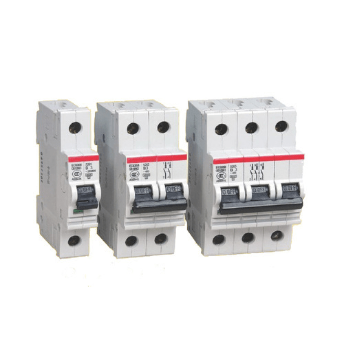
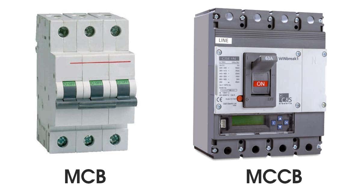
Electrical Circuit Breaker

Electrical Circuit Breaker |

Operation and Types of Circuit Breaker

Electrical Circuit BreakerWhat is Circuit Breaker?

An electrical circuit breaker is a switching device which can be

operated manually and automatically for controlling

and protecting an electrical power system.

As the modern power system deals with huge currents,

special attention should be given during designing of a circuit breaker to ensure it is able to safely

interrupt the arc produced during the closing of a circuit breaker.

This was the basic definition of circuit breaker.

Introduction to Circuit Breaker

The modern power system deals with huge power network and huge numbers of associated electrical equipment.

During a short circuit fault or any other type of electrical fault (such as electric cable faults),

a high fault current will flow through this equipment as well as the power network itself.

This high current may damage the equipment and networks permanently.

For saving these pieces of equipment and the power networks,

the fault current should be cleared from the system as quickly as possible.

Again after the fault is removed,

the system must come to its normal working condition as soon

as possible for supplying reliable quality power to the receiving ends.

In addition to that for proper controlling of the power system,

different switching operations are required to be performed.

So for timely disconnecting and reconnecting different parts of power system network for protection and control,

there must be some special type of switching devices which can be operated safely under huge current carrying condition.

During the interruption of large current,

there would be large arcing in between switching contacts,

so care should be taken to quench these arcs in circuit breaker in a safe manner.

The circuit breaker is the special device which does all the required switching operations during current carrying condition.

This was the basic introduction to circuit breaker.

Working Principle of Circuit Breaker

The circuit breaker mainly consists of fixed contacts and moving contacts.

In normal “ON” condition of the circuit breaker,

these two contacts are physically connected to each other due to applied mechanical pressure on the moving contacts.

There is an arrangement stored potential energy in the operating mechanism of circuit breaker

which is released if the switching signal is given to the breaker.

The potential energy can be stored in the circuit breaker by different ways like by deforming metal spring,

by compressed air, or by hydraulic pressure. But whatever the source of potential energy,

it must be released during operation.

The release of potential energy makes the sliding of the moving contact in a speedy manner.

All circuit breaker have operating coils (tripping coils and close coil),
whenever these coils are energized by switching pulse,

and the plunger inside them displaced.

This operating coil plunger is typically attached to the operating mechanism of circuit breaker,

as a result the mechanically stored potential energy in the breaker mechanism is released in forms of kinetic energy,

which makes the moving contact to move as these moving contacts mechanically

attached through a gear lever arrangement with the operating mechanism.

After a cycle of operation of circuit breaker the total stored energy is released

and hence the potential energy again stored in the operating mechanism of the circuit breaker

using spring charging motor or air compressor or by any other means.

Till now we have discussed mechanical working principle of circuit breaker.

But there are electrical characteristics of a circuit breaker which also should be considered in

this discussion of the operation of the circuit breaker.

Let’s have a discussion on electrical principle of circuit breaker.

The circuit breaker has to carry large rated or fault power.

Due to this large power, there is always dangerously high arcing between moving contacts

and fixed contact during operation of the circuit breaker.

Again as we discussed earlier the arc in circuit breaker can be quenching safely

if the dielectric strength between the current carrying contacts of circuit breaker

increases rapidly during every current zero crossing of the alternating current.

The dielectric strength of the media in between contacts can be increased in numbers of ways,

like by compressing the ionized arcing media since compressing accelerates the deionization process of the media,

by cooling the arcing media since cooling increase the resistance of arcing path or by replacing the ionized

arcing media with fresh gasses. Hence some arc quenching processes should be involved in the operation of the circuit breaker.

Although circuit breakers perform their function independently and without supervision,

there are also remote control circuit breakers which can be operated on demand at a distance.

Types of Circuit Breaker

According different criteria there are different types of circuit breaker.

According to their arc quenching media the circuit breaker can be categorized as:

  1. Oil circuit breaker.
  2. Air circuit breaker.
  3. SF6 circuit breaker.
  4. Vacuum circuit breaker.

According to their services the circuit breaker can be categorized as:

  1. Outdoor circuit breaker.
  2. Indoor breaker.

According to the operating mechanism of circuit breaker they can be categorized as:

  1. Spring operated circuit breaker.
  2. Pneumatic circuit breaker.
  3. Hydraulic circuit breaker.

According to the voltage level of installation types of circuit breaker are referred as-

  1. High voltage circuit breaker.
  2. Medium voltage circuit breaker.
  3. Low voltage circuit breaker.

ما هو مرحل الحمل الزائد (الاوفر لود): أنواعه وتطبيقاته

يسعدنا زيارتكم صفحاتنا على مواقع التواصل الاجتماعي حيث نقوم بنشر عروض حصرية على موقعنا الالكتروني.

صفحتنا علي الفيسبوك هنا.

حسابنا على تويتر هنا.

Posted on Leave a comment

1 Why We Need Electricians

Why We Need Electricians
The man is repairing the switchboard voltage with automatic switches. Electrical background

Why We Need Electricians

Why do people need a electrician?

Most people think that when they are building a new home,

that is the only time that they would need a electrician.

But actually you need electricians for doing a lot more then that one particular job.

If you own a home and have problems with your electricity you should call a electrician.

A electrician can fix your electrical jobs safely.

It is far better to call a electrician then to try and do the job yourself and then end up doing something wrong.

If you don’t do the job right it can be dangerous and could cause a fire in your home.

And also down the road it could be costly if your have to call a electrician in to do the job right.

benefits of having electricians

Electricians are trained to know what they are doing and they can do any electrical job right.

Newer and older homes should have the electrical wiring checked out and inspected before purchasing the home.

This will save money if they find out that it is faulty or in need of updating.

A electrician will come in handy to make the wiring safe in any home.

Some people try and do electrical jobs their selves but if you do you will always wonder if you did everything right or not.

GAHZLY.COM
GAHZLY.COM

where to find

You can usually find a electrician in the phone book if you need one.

You can also find a electrician on the internet by looking through local ads.

Some people will ask around in their community if anyone would know of a good electrician.

A electrician can be found a number of ways.

By searching for a electrician like this you can save money in some cases and

find a electrician close to your home that will do good work for you.


A electrician can do many types of electrical jobs.

Some electricians will not only work on homes, but will also do the wiring of security systems.

It all depends on what type of electrical job you need to have done.

A electrician will do work when a new home is being built to wire it correctly.

And electricians also work on construction sites when buildings are being put up.

When picking out a electrician try and find one that is licensed, well known by others and good at what they do.

Like any professional some electricians are better and more experienced at what they do then others.

Check them out first before you hire them to do work for you.

There is nothing wrong with finding more information out about them.

Being a licensed professional is important to know if you need a job done.

It will tell you that they have had training and put in hours of schooling to know how to do the job right for you.

A electrician is a professional that we need for many jobs around our home.

They make sure that our homes are wired safely.

It is a good idea to call a licensed electrician for all the electrical jobs around our home.

When Should We Hire A Electrician

It is easy to know when we should hire an electrician.

Some of the jobs in our home are just to much for us and we don’t have the proper understanding

and knowledge of how to fix and repair them.

Electricity can be very dangerous and is not worth taking the risk of being hurt by doing

a job that you are not sure how to do in the first place.

follow us on our social media :

Facebook=> Gahzlystore

twitter=> Gahzlystore

Visit our website: GAHZLY