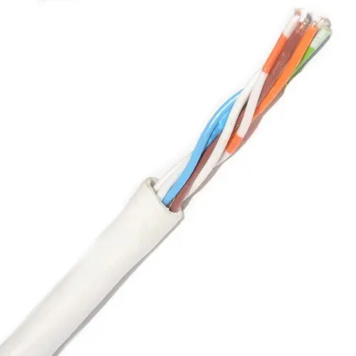
Electrical transformers
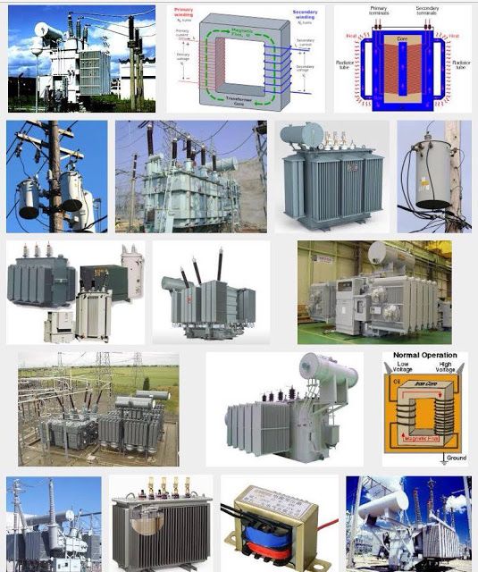 Electrical transformers
Electrical transformers are considered one of the most important elements of the electrical network (1 phase or 3 phase), widespread and diverse in their shapes, sizes and functions.
Electrical transformers are very widespread in the electrical system due to their importance and role in electrical circuits.
Historical introduction to the electrical transformer
The English chemist Michael Faraday was the first to discover the phenomenon of mutual induction between the two separate coils located on a core made of magnetic material.
During his experiment, he began to measure the electromotive force. Electric Motive Force) is practically in one of the two coils due to the change of current in the other coil.
Transformers appeared for the first time in 1882, made of one primary (primary) winding and several secondary windings, with the aim of obtaining several values of voltages of different values.
Magnetic heart transducers began to appear
(in English: magnetic core) for the first time in 1884 AD. It is the starting year for the use of transformers in converting Electrical energy to raise the values of voltages and transmit them to long distances.
And then the Hungarian scientist “Wire” came up with the name of the transformer on these devices, And then he came up with the idea of connecting transformers in parallel,
The 3 won electrical transformer was invented by the Russian scientist “Dolev Dobrovolsky”.
Definition of electrical transformer
The converter is known as: Transformer: It is a static (non-kinetic) electrical machine that works to convert alternating current of a certain voltage to another alternating current of other voltages, and the voltages may be higher or lower with the stability of power and frequency. To carry out the transfer of electrical energy from the place of its generation to the place of consumption.
The electrical transformer can be defined in another way as an electrical machine capable of converting the electrical power entering it with a certain effort into electrical power coming out of it with a different effort, whether increase or decrease.
Magnetic Principles of Electrical Transformers
Magnetic Principles of Electrical Transformers
magnetic principles of electrical transformers, It is necessary to know the details of the magnetic effect and the field created by the passage Electric current in electrical transformers .
There are some magnetic rules and foundations that must be studied before entering into the details of transformers, So what are the magnetic principles of electrical transformers and how do they work.
magnetic effect
It results from the presence of an ordinary magnet. magnet) somewhere in the presence of what is known as a magnetic field region, It is the area where the so-called flood lines appear (in English: Flux Lines), Which consists of lines running from the north pole to the south pole of the magnet.
We can feel it and see its direction if we put iron filings near a magnet, as shown in the following picture:
the magnetic field
Magnetic field and electric current
Faraday proved that any alternating current flowing through an electric wire, It will generate a magnetic field similar to the magnetic field that arises around an ordinary magnet.
The direction of this magnetic field is determined by Fleming’s right-hand rule. Hence the term electromagnetism.
Which means that electricity and magnets have mutual and similar relationships and effects.
It is stated that we cannot obtain a strong magnetic field from ferrous magnets,
We have taken advantage of the fact that the current passing through a wire is accompanied by a magnetic field, The same principle was applied to the files,
Where the direction of the current is the same in all the windings, Hence, a strong magnetic field is generated. It is stronger than the field originating from one or two wires.
And the above happens in transformers, As the windings are wrapped around the arm of the iron core, a strong magnetic field is created in it, which represents a longitudinal section in the iron core of the transformer.
The magnetic field associated with an electric current
Magnetic driving force
There are some laws and relationships that govern the work of this magnetic field arising due to the passage of an electric current, As if an electric current passes through a coil with a number of turns N, then magnetic forces are generated, the value of which is estimated by the following relationship:
MMF = NI
And the driving force is responsible for pushing the lines of flux in the iron core. The shorter the magnetic field force pushes the flux lines, the greater the field strength.
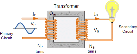
The importance of electrical transformers
The importance of electrical transformers
The importance of electrical transformers,
The presence of electrical transformers in the power system is of great importance and has many uses in transmission and distribution lines, especially in household electrical appliances.
There are also electrical transformers single-sided transformers and three-faceted transformers, Follow us to learn about the importance of electrical transformers in our daily lives.
What is an electrical transformer?
An electrical transformer is defined as a static (non-moving) electrical machine whose function is to convert an alternating current of a certain voltage to another alternating current of other voltages either up or down with stability in power and frequency. The electrical transformer is used to transfer electrical energy from the places where it is generated to the places where it is consumed.
The difference between transformers, generators and motors
Although the term electromechanical Electric Machine)
Always referring to generators and engines of all kinds,
However, a transformer is also a type of electrical machine. This is because the laws that govern the work of motors, generators and transformers are the same and they are the laws of electromagnetism.
The only difference between motors and generators on the one hand and transformers on the other hand is that motors and generators rely on the principle of motion (spin) while transformers are a static electric machine that does not rotate.
Other than that, they are all subject to the laws of electromagnetism.
The importance of electrical transformers
The importance of electrical transformers mainly lies in converting the electrical power entering it with some effort into electrical capacity coming out of it with a different effort, whether it is increased or decreased.
The transformer is used as a main element in transmission lines in order to transmit electrical energy with high voltages over longitudinal distances with minimal energy losses.
Advantages of using electrical transformers
The main advantage of transformers in the electrical power system is to reduce the value of the current transmitted through lines and cables, This feature has several other advantages:
- Minimizing the power lost during electrical power transmission.
- Reducing the value of the drop in voltage.
- Reducing the cost of transmission lines and electric power towers.
Conclusion: Electrical transformers have an essential role in organizing and transmitting electrical energy across transmission lines for longitudinal distances with the least possible losses in terms of voltage drop and lost capacity.
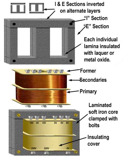
electrical transformer parts
The electrical transformer consists of several basic and simple parts, which are as follows:
represents the magnetic circuit,
It consists of a group of thin sheets of magnetic iron ranging in thickness from 0.35 mm to 0.5 mm and are isolated from each other.
The plates are pressed together with nails or screws to form a suitable path for the magnetic flux lines.
The electrical circuit in a transformer, It consists of the following:
- Primary files: It consists of coils of insulated copper wire, And connected to the electrical source.
- Secondary files: It consists of coils of insulated copper wire, And through it provides the load with electrical energy.
How does an electrical transformer work?
The idea of working the electrical transformer is based on the principle of electromagnetic induction, which states that the value of the driving force is directly proportional to the rate of change of the magnetic flux.
Therefore, the transformer cannot be used in DC systems because it produces a constant magnetic field whose change is equal to zero.
Types of electrical transformers
Electrical transformers are classified in terms of their use into two main types:
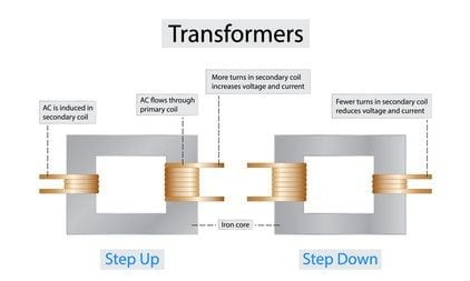
electric hoist transformer: (in English: Step-up Transformer) These transformers are used to increase the voltage value while decreasing the current in the secondary winding for power stability,
The number of turns of the primary coil is less than the number of turns of the secondary coil.
step-down transformers: (in English: Step-down Transformer) These transformers are used to reduce the voltage value with constant power and thus increase the current value in the secondary winding,
The number of turns of the primary coil is more than the number of turns of the secondary coil.
 Types of electrical transformers
Types of electrical transformers
types of electrical transformers, All kinds of electrical transformers are used to transmit Electrical energy from one circuit to another at the same frequency with increasing or decreasing voltages.
The need to use the electrical transformer has begun to transmit the high energy generated in the generation plants with the least possible amount of loss and the lowest costs.
What are the types of electrical transformers in terms of the nature of conversion and use.
Types of transformers in terms of iron composition
- Core type: The iron core is made of thin sheets of steel in the shape of a rectangle. Coils (primary and secondary) are placed on both ends of the iron core.
- Shell type: This type has steel plates in the form of three legs and the insulated coils are wound apart around the middle leg.
Types of transformers in terms of iron composition
Types of transformers according to the number of faces
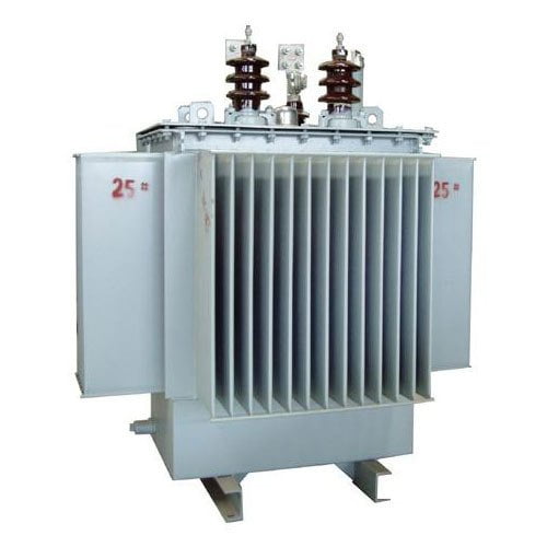
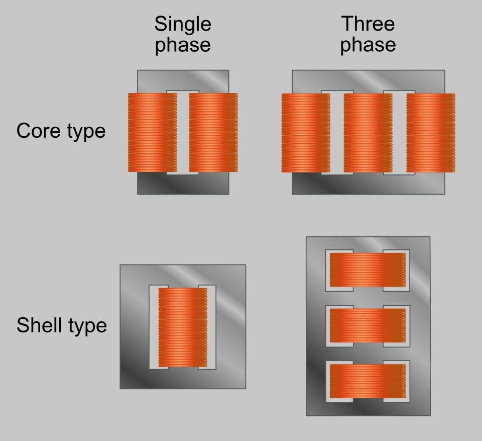 Single phase electrical transformer: This type of transformer is found in household electrical appliances and chargers.
3-phase (3-phase) electrical transformer: It is used in solar energy transmission lines as well as in electrical distribution for homes, factories and large buildings.
Types of transformers in terms of use
Types of electrical transformers are classified by uses into:
- power transformers: These transformers are used in generation and transmission substations, They are characterized by high capacities.
- Distribution Transformers: Used in the regulation and distribution of energy for consumption.
- Isolation Transformers: They are used to isolate the source of electricity from the load. These transformers are found in various laboratories and workshops. The number of turns of the primary coil is equal to the number of turns of the secondary coil.
- Measurement adapters: Measurement transformers are divided into voltage transformers (VT) and current transformers (CT).
- Feed source adapter: It is used in small chargers to reduce voltage.
- welding transformer: It is a dry, natural air-cooled single-phase step-down transformer, The voltage on its two ends in the case of no-load ranges between 60 to 75 volts to ignite the electric arc.
Types of transformers in terms of conversion
- Step-up transformer.
- Step-down step-down transformer.
Types of transformers in terms of frequency
- Very low frequency transformer.
- High frequency transformer.
- Very High frequency transformer.
Types of transformers in terms of insulation
- Oil-immersed coil converter Oil Immersed).
- Converter whose coils are immersed in ascarl. Askarel Immersed).
- Transformer coils are insulated with fluid silicon. Silicon Fluid).
- dry transformer Dry Type).
- The dry transformer whose tank is filled with resin. Cast Resin).
Advantages of using electrical transformers
The most important features of electrical transformers are as follows:
- The possibility of raising and lowering the value of voltage and current.
- Reduces power loss during long distance transmission of electrical energy.
- Decrease the voltage drop.
- Reduce the cost of transmission lines and electric power towers.
Function of electrical transformers
Function of electrical transformers
transformer function, The presence of the electrical transformer has a major and essential role within any part of the electrical network system.
Whether it is within the generation, transmission, distribution or distribution network.
Since the primary role of electrical transformers is to lower or raise the value of voltage and current ,
Whether through transmission lines and cables or in electrical distribution lines.
Let’s get acquainted with the function of electrical transformers, And do these converters have one function, or can they be used in several different functions, depending on the nature of the network in which they are located?
The role of electrical transformers
There are many roles these transformers can fulfill, for example:
Transmission transformers that contribute significantly to the transmission of electrical energy over long distances from generating stations to transmission lines, then to distribution transformers, and finally to electrical loads.
When we want to transfer electric power from the generating station to the transmission lines without using a step-up transformer,
What happens is we’re faced with a very high current problem, Which needs an incredible number of transmission cables.
To solve the problem, a transformer must be installed. In order to raise the voltage to times the voltage generated in the generating station by 20kV/500KV (it may vary from one country to another).
As a result of what happens when the voltage is raised immediately after the generator, It is to reduce the current to the lowest possible value with constant power. Then we can use a small number of cables.
Types of electrical transformers
There are many types of transformers in terms of: uses,
number of beats, Depending on the cooling method, conversion ratio and operating frequency, But we will focus on two types in terms of the nature of use only, namely:
- Step-down transformer: In which the voltage is raised and the current decreased with constant power. Like: transport adapters.
- Step-down transformer: In it, the voltage is reduced while the current value is increased while the capacity is constant. Like: distribution transformers.
Function of electrical transformers
There are many different functions of transformers of different types, as we mentioned in the types of electrical transformers , and these functions include:
transmission adapters:
Its function is to raise the voltage of the electrical energy generated by the power station to multiples of the voltage generated. In order to reduce the value of the current while the generated power remains constant,
In order to reduce the power lost during electrical power transmission, It is more practical by reducing the cross-sectional area of the transmission lines.
These transformers are placed directly after the generators in the generating station.
transport adapter
Distribution Transformers: Its function is to reduce the voltage in accordance with the voltage of the electrical network feeding factories and homes. Raising the current with constant capacity.
distribution transformer
There are also autotransformers used in many applications, the most famous of which are placed inside the house, In order to regulate and stabilize the voltage of the electrical network inside.
Electrical transformer installation
Electrical transformer installation
transformer installation, The presence of the electrical transformer has become necessary in the electricity network, whether power electricity or home electricity,
The transformer is only a transmitter of electrical energy and not a producer of it.
Where the electrical transformer is generally used in power electrical systems to transmit power, Even in the operation of electrical devices with an appropriate voltage, it is determined by the voltage of the device.
A brief history of the electrical transformer
He was the first to discover the phenomenon of mutual induction. Mutual Induction) is Faraday in 1838,
Where he placed two separate coils on a heart made of magnetic material, He practically measured the electromotive force in one of the two coils as a result of the current in the other coil.
Transformers made from one primary winding and several secondary windings were first introduced in 1882 with the aim of obtaining different values of secondary voltages.
Magnetic core transducers are used to convert electrical energy to high efforts, And transported long distances in 1884.
Brothers John and Edward Hopkinson first made a simple transformer consisting of insulated steel plates. It has two coils, one for low voltage and the other for high voltage.
The first person to call these devices a transformer was the ductwork scientist Wiri. He later invented the idea of connecting transformers in parallel.
Finally, the Russian scientist “Dolev Dobrovolsky” invented the triple transformer in 1889.
Three phase electrical transformer
Reasons for the spread of electrical transformers
We all know that the role of the electrical transformer in transmission lines is to reduce the value of the current transmitted through lines and cables, reduce energy loss, Facilitating the transmission of electrical power.
As the generating stations produce enormous electrical energy by using several huge generators,
It is illogical to transfer this energy produced with the same voltage and high current, which requires a large and imaginary amount of cables of large diameters.
Here comes the role of the electrical transformer,
Where it works to raise the value of the voltage to double values, Like: Step up transformer 20/500 kV, It means that it is able to raise the voltage to become the transmission voltage 500kV instead of 20kV.
The purpose is to reduce the current value to the lowest possible value and therefore we need less number of cables and less diameter.
Electrical transformer installation
The electrical transformer is composed in its simplest form of an iron core. Iron Core) wrapped on both sides of the coils, They are:
Primary file: (in English: primary winding), Which is the coil that connects directly to the power source, It consists of a certain number of turns (Np).
secondary file: (in English: Secondary Winding), It is connected to the load directly on its edges or through transmission lines, It also consists of a number of turns and is denoted by the symbol (Ns).
It is considered the most important two main components in the composition of the electrical transformer, They: Iron core and coils.
 Fields of use of power transformers
Fields of use of power transformers
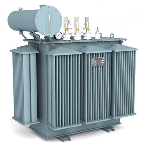
Fields of use of power transformers, It is considered converter The most widespread and diverse elements of the electrical network in its shapes, sizes and functions, Where the transformer is located in the generation networks, transmission and distribution lines.
It has become necessary to study the areas of use of power transformers due to its diversity in size, shape and function within the electrical power system.
Definition of a power transformer
It is a non-moving electrical component whose function is to convert alternating current of a certain voltage to another alternating current of another voltage (higher or lower) with constant power and frequency.
Its mission is to transfer electrical energy from the areas of generation to the areas of consumption.
Power transformer 500 kVA
Installing power transformers
The transformer consists of three basic components:
- iron heart Core).
- Primary file Primary Winding.
- secondary file Secondary Winding
While power transformers are added additional components such as:
- Main oil tank Main Tank).
- oil pump oil pump).
- Radiator Radiator).
- expansion tank Conservator).
- cooling fans Cooling Fans).
- voltage regulator Tap Changer).
- high voltage penetration insulator HV Pushing).
Powerful transformer with cooling fans and oil tank
Fields of use of power transformers
There are many areas of use of power transformers and they are divided into:
There is a dedicated transformer that is placed near the generating stations and its purpose is to raise the voltage from the generation voltage level to the transmission voltage level.
These transformers are located in transmission transformer stations. transmission Substation) which are close to the generating stations.
- voltage step down transformers
Its function is to reduce the voltage from the transmission voltage to the level of the distribution efforts according to the system followed by each electricity company.
- Distribution Transformers
It is the one that distributes electric power to subscribers and ends with distribution transformers that reduce the voltage to 220 volts or 110V according to the system followed by the Electricity Company.
Function of up-and-down transformers
These transformers are called power transformers. Its mission is to raise or lower the effort to the required level in every part of the system. In addition to containing the power transformer, the station performs the following functions:
- Operation of the circuit breakers in the event of a fault in the transmission line or in the station itself.
- Control the flow of power to a specific area.
- Contain protection devices, voltage and current transformers for protection and measuring devices.
- It also contains disconnecting and connecting fixtures and equipment that allow maintenance of any of the station’s equipment without cutting off service to any area served by the station.
Electrical transformers

We are pleased to have you visit our pages on social networking sites, where we publish exclusive offers on our website.
Our Facebook page here .
Our Twitter account is here .

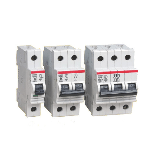 What is Circuit Breaker?
 All circuit breaker have operating coils (tripping coils and close coil),
 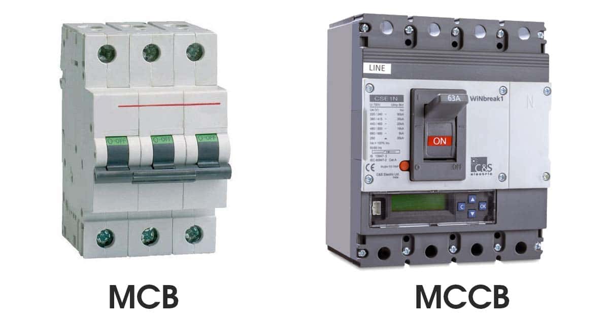 Types of Circuit Breaker