
Posted on Leave a comment

Electrical Contactor Connection and Wiring 1

Electrical Contactor Connection and Wiring

Hey, in this article we are going to see proper electrical contactor connection and wiring diagram for normal operation, star-delta starter, motor control, light control, etc. Also, we will discuss the internal circuit diagram of the contactor used for power control.

What is Electrical Contactor?

In simple words, Electrical Contactor is an electrically operated switch whose main function is to connect or disconnect the load from the power source. Basically, the contactor work as a medium when we control a high voltage, high current power circuit by a low voltage, low current control circuit.
Contactor Symbol:
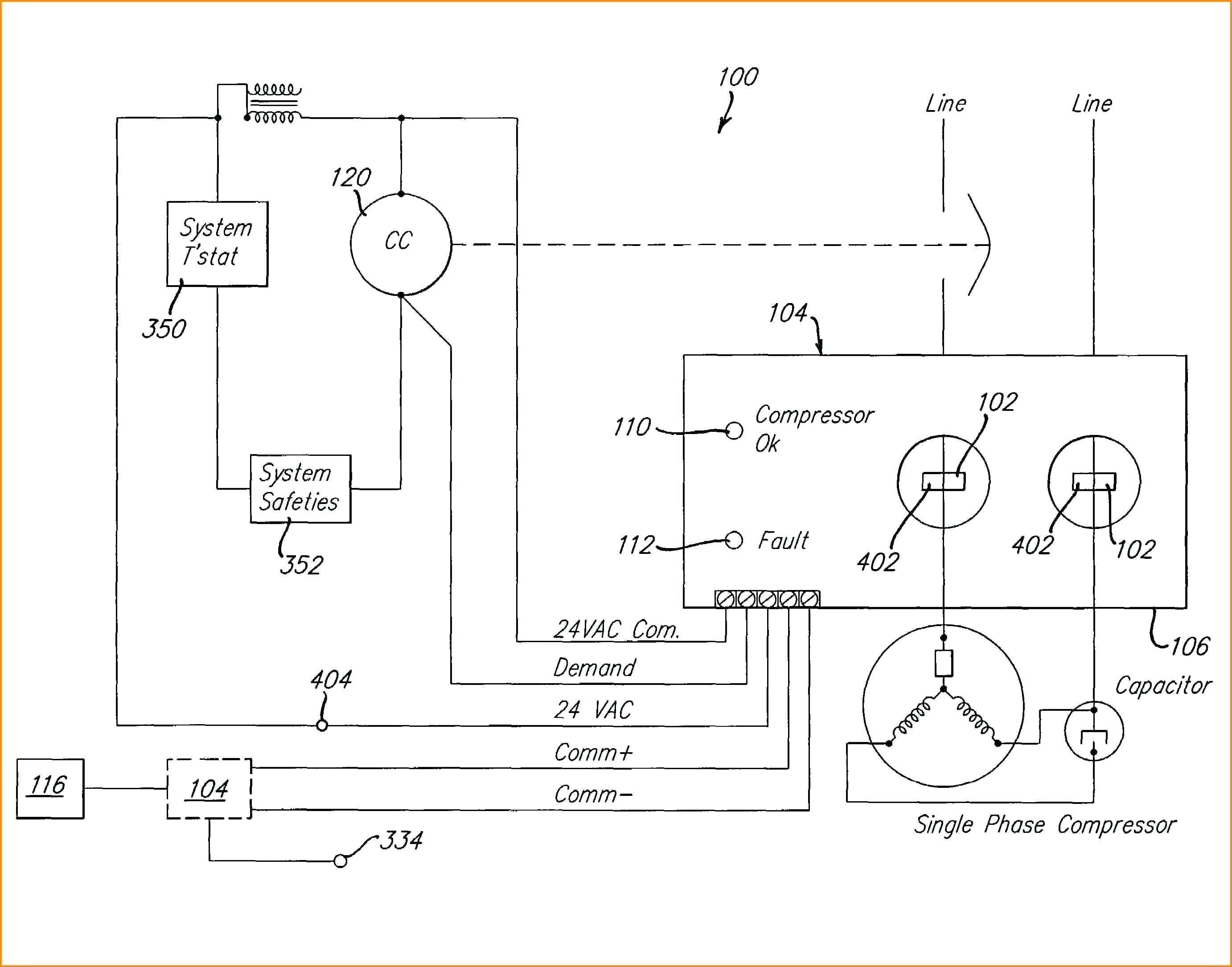
Electrical Contactor Connection and Wiring

Contactor Terminals and Contacts

Before you going to do a connection for a contactor you must know about its terminals and contacts. Basically, a contactor has two types of contacts – 1. Main or Power Contacts and 2. Auxiliary Contacts
In the below figure, you can see there is a total of 16 terminals in the contactor.
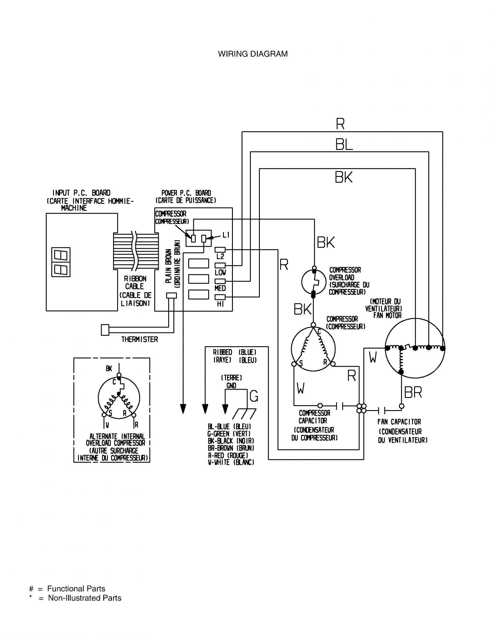
A1 and A2 are magnetic coil terminals.
L1, L2, and L3 are the incoming terminals of the main contact which are to be connected to the main power supply.
T1, T2, and T3 are the outgoing terminals of the main contact which are to be connected to the load.
Here two NC and two NO auxiliary contacts are available. Each of them has two terminals.

Contactor Connection Procedure

1. Generally the magnetic coil of a contactor is designed to operate at a low voltage such as 230V AC, 110V AC, 24V DC, etc. So provide the power supply to the magnetic coil as per requirement.
2. Connect the main power supply terminal with the incoming terminals of the contactor.
3. Connect the load with the outgoing terminals of the contactor.

Contactor connection with Push Button Switch

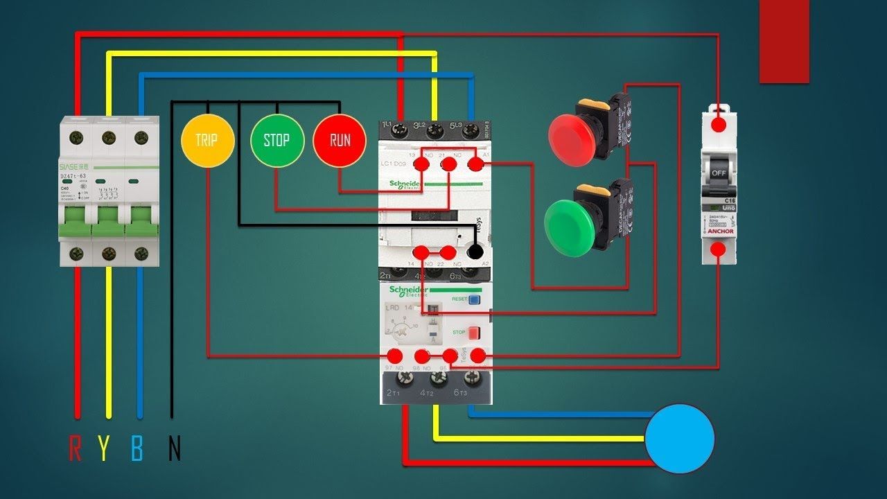
Now we are going to see, how to connect the push button switch with a contactor. Here the connection diagram in the below figure.
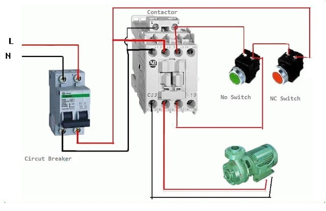
You can see here, two push button switches are used. NC push button(green colour) switch is used to turn off the contactor whereas the NO push button(Red colour) switch is used to turn on the contactor.
These pushbutton switches break or make the contacts only when we press the button. Once we release the button its contacts also come back to their old position. So the magnetic coil of the contactor is also connected through the NO auxiliary contacts. So the contactor will be turned on once we press the switch and remain On even when we release the NO push button. The contactor will remain turned on until we press the NC push button.

Contactor connection with Indication Lamps

Now, let’s go to know how to connect indication lamps with a contactor to give indications whether it is in ON condition or OFF condition. See the below diagram.
Here we have taken two indication lamps – Red for ON, Green for OFF.
You can see the Red indication lamp is connected through the NO auxiliary contact. So when the contactor turning on it will glow. On the other hand, the green indication lamp is connected through the NC auxiliary contact. So when the contactor is in OFF condition, this lamp will glow. Once the contactor is turned ON it will off and the red colour lamp will glow.

Contactor Connection with Thermal Overload Relay

Thermal Overload Relay is mainly used to give protection against overload fault. So thermal overload relay used with electrical contactor when we designed DOL Starter, Star Delta Starter, etc.
Here you can see the connection of thermal overload relay with a contactor in the DOL Starter Circuit.

كيفية توصيل القواطع الكهربائية المنزلية

lightning
We are pleased to have you visit our pages on social networking sites, where we publish exclusive offers on our website.

 Facebook page here.

Twitter account is here.

Posted on Leave a comment

How to Install Electrical Wiring System Properly?

How to Install Electrical Wiring System Properly?

Concealed Conduit Electrical Wiring systems are the most popular, aesthetically appealing, and most common type of House Electrical wiring used.  Conduit wiring is a professional way of wiring a building. Mostly PVC conduits are used in domestic wiring.


The conduit protects the wires from external damages like rodents etc., increasing the longevity of the wires used. Before talking about the installation procedure, lets talk about what house electrical wiring system is and their different types.

Different Types of House Electrical Wiring Systems

House Electrical wiring is distributing the electricity (electrical energy) from suppliers meter board to various appliances in the home like lights, fans, TV etc., There are lot of different types of house electrical wiring systems used in India and other countries. Few of them are:

1. Cleat Wiring

Cleats with groves are used to hold the cable. It is a temporary wiring system so not used in typical house constructions

How to Install Electrical Wiring System Properly?

2. Casing Wiring

Open wiring system where the wires are run through casing enclosure and capping is used to cover the casing.

Casing and Capping Electrical Wiring

3. Batten Wiring

Single or a group of wires are laid over a wooden batten. The wires are hold to the batten using a brass clip, which is attached to the wooden battens at an interval of 10-15 cms

Batten Wiring

4. Surface Conduit Wiring

PVC or GI conduits are laid on the surface of the wall or ceiling. These conduits are attached to the walls with a 2-hole strap and base clip at a regular certain distances. Electrical wires are laid inside the conduits.

Surface Conduit Installation

5. Concealed Conduit Wiring

PVC conduit pipes are placed inside the chiselled brick/block wall before plaster. The wall is later completely plastered and painted. Electrical wires are laid inside the conduits. This type of wiring are aesthetically appealing since they are no electrical wires/conduits seen on the top of the wall.

Concealed Conduits Installation

Advantages and Disadvantages of Concealed Conduit wiring System

Advantages of Concealed Electrical Wiring System

  • It is the safest wiring system of all the ones mentioned above
  • It is Aesthetically appealing
  • There is no risk of fire or mechanical wear and tear
  • There is no risk of damaged cable insulation
  • It is safe from humidity, chemical affects and smoke
  • There is No risk of shock
  • Its most Reliable and popular wiring system
  • Do not hamper interior layout as conduits are concealed in wall
  • Renovations can be easily performed as old wires can be easily replaced

Disadvantages of Concealed Electrical Wiring System

  • Its expensive when compared to other surface conducting methods
  • Its very hard to find any defects in the wiring
  • Adding additional conduit in future is cumbersome (Needs wall chiselling and finishing)
  • Changing of location of appliances or switches is difficult
  • Installation is difficult as compared to other methods
  • Complicated to add/manage additional connection in the future

Step by Step Procedure to Install Concealed Conduit Wiring System

Step-1: Laying of Electrical Conduit in Slab

  • Slab conduits for house wiring should be done in 2 mm thick 25 mm size FR PVC conduits. Preferably Slab conduits shall be laid in between top and bottom reinforcement. Please ensure concrete thickness i.e. cover to PVC Conduits incase of singly reinforced slabs.
  • Only Deep junction boxes shall be used in slabs. With Binding wire, properly bind the PVC conduits
  • Preferably follow different color coding for conduits for data (LAN wire, telephone wire etc.,) and electrical wires
  • Use grey PVC pipes for data and black PVC pipes for electrical wires. Use PVC solvent for jointing the accessories
  • Wall drops shall be properly checked for face of wall/beam. Please ensure concrete thickness i.e. cover
  • All the conducting shall be checked as per services drawing, which contains locations of switchboards and number of points to be installed at each location.
  • Special precaution shall be taken during concreting of slab.
    • All broken pipes are to be replaced
    • All joints have are to be watertight joints to avoid choke up)
  • GI wire passing shall be carried out immediately after de-shuttering of slab & beam. (any choke up to be documented and alternate routing to be shown  in shop drawings and documented for future references).
  • All necessary sleeves shall be provided in beams, columns, prior to slab casting as per electrical & air-conditioning.
  • Pull boxes shall be provided at suitable locations.
  • The pull and junction boxes shall not be clustered at one place and shall be so arranged that they should not be easily seen from heavy movement areas as per electrical drawings.

Step-2: Laying of Electrical Conduits in Walls

  • The concealed conduit work shall be carried after construction of masonry walls but prior to plaster.
  • Chasing work shall be carried out after completion of curing of brickwork (at least 7 days gap from brickwork).
  • The wall chasing should be done with wall cutters only,this would avoid damage to walls.
  • The conduits shall be fixed with approved clips to ensure proper routing and wiring later.
  • After fixing the conduits, boxes, and accessories, the chiseled surface should be filled with cement mortar and chick mesh wrapped  around conduits.
  • Wall conducting activity shall start with level marking on the wall (usually box level),knowing its height above FFL(Finished floor level)
  • The width of chasing shall be limited as per number of conduits.
  • The depth of chasing to have conduit recess at least 10mm from masonry wall.
  • All horizontal conduit runs shall be straight at box level. Light point conduit shall run straight vertical to switch box. No wall conduit shall be taken haphazardly.
  • No Elbows & bends shall be used. In case of change in direction in pipe use spring to bend the pipe.
  • Power conduits should not be run near any communication line.
  • Conduits above false ceiling shall run with proper supports / suspenders. Conduits shall not be rested on false ceiling grid in any case. All vertical runs with open ends shall be sealed at top in case of false ceiling work, while masonry civil works going on.

Step-3: Installation of Switch Board Back Boxes

  • All concealed switch board shall be fixed properly in level as per given schedule (Height, distance from Finished Floor (FFL) should be as per architect’s recommendation)
  • The gap between two concealed switch boards shall be uniform & maintain same for all installation.
  • The switchboards shall be readymade modular type metal boxes of approved makes & drawing.
  • Concealed box shall be fixed 3 mm below the plastered surface.
  • Box fixing shall be done before plastering work along with wall conduiting. These boxes shall be filled with thermocol while plastering work.

Step-4: Installation of Distribution Boards

  • DB’s shall be concealed before plaster work
  • DB box shall be fixed in proper line & level in the recess provided in brickwork
  • DB’s shall be ready-made as per design (fixing no. of conduits pipe entering DB)
  • All PVC pipes shall enter in to DB from given entry holes only

أفضل المشتركات الكهربائيةلمعرفة اخر المنتجات الخاصة بنا وعروضنا المميزة يرجى الاشتراك بصفحاتنا على مواقع التواصل الاجتماعي:

صفحتنا على الفيسبوك=> Gahzlystore

صفحتنا على تويتر=> Gahzlystore